

Table of Contents
whats is Freecad |
Is primarily a parametric 3d modleing software. Though it also has 2d drafting tools these to extract drawings from models or create them from scratch. |
what is a work bench |
A work bench is a collection of tools used to perform certain tasks. In this tutorial thework benches that will be focused on will be the draft work bench, the arch workbench and the tech draw workbench. |
Draft work bench |
This is a collection of 2d drafting tools , including; points, lines , poly lines, circles , other geomtric shapes and the means to dimmension and modify them |
Arch work bench |
Has some cross over with the draft work bench, it is a collection of tools that deals primarily with the creation of building components such as wall, slabs roofs and windows. |
Tech draw work ben |
This is a collection of tools used to place 2d drawings and views of 3d objects on to a virtual representation of a paper . Here drawings from different workbenches can be scaled, rotated and further annotated |
|
|
|
LHS |
|
|
function |
command |
Icon |
tips |
Multi select |
Ctrl,+ select |
- |
|
Box select |
Shift+e |
- |
Click once and move mouse over objects |
Zoom in and out |
Ctrl + middle + (move mouse) |
- |
These commands vary per the navigation style hovering your mouse of the current style will reveal how to navigate |
Pan |
Shift + middle (mouse move) |
- |
|
Point |
Has no keyboard shortcut. Select it in the tool bar |
|
Indicate with the mouse by selecting an arbitrary placement or key in coordinates in the task tab of the combo view. |
line |
Press ‘l’ then ‘i’ |
|
There exists 3 modes of input ; arbitrary where you simply indicate the start and end point with select on your mouse after entering the shortcut
precise/ global coordinates grid with the use of coordinates one can key in the coordinates of the start and end relative to the origin (global) of the grid or a point. The grid can be altered in preferences |
Poly Line |
press‘p’then ‘v’ |
|
|
move |
Press ‘m’ then ’v’ , select pivot, select destination |
|
|
rotate |
With an object selected press ‘r’ then ‘o’ or select the object after the command. |
|
|
fillet |
Press ‘f’ then ‘i’ |
|
|
rectangle |
Press ‘r’ then ‘e’ |
|
|
circle |
Press ‘c’ then ‘i’ on the keyboard |
|
The first point determines it’s location and the second determines its radius from that point |
B- spline |
Press ‘b’ then ‘s’ |
|
- |
Views |
1:front, 2 ,3 ,4 ,5 |
|
- |
Hide/ show |
spacebar |
- |
Select the object first (it still apears in the combo view when hidden |
Snap points on/off |
shift+s |
|
|
upon entering or selecting a command the tasks tab in the combo view will open giving options on the properties of the object being created tip: all created object cand have their properties altered by selecting them in the combo view under the tab model and |
|||
|
Menu items |
Description |
Tips |
Combo view
|
The combo view consits of 4 tabs; Model, tasks view and data.
|
|
Tool bar |
Displays the current tools of the active work bench
|
|
Navigation style |
Freecad has multiple styles of navigation so that one can more easily use it. Selecting the cad style; uses the more generic navigation one comes to expect fromcad programs like libre cad hovering over the navigation style menu reveals, the mouse layout for the selected style |
|
Workbenches |
Work benches are a set of tools ment to perform a specified task |
|
Working plane |
The face or axii which one creates 3d or 2d objects on |
|
|
Preferences has the default settings for each work bench
|
|
|
*linux is case sensitive
* key diffrences in windows and linux
Opening and Navigating a Project
|
|
Tasks
|
expand the groups in the combo view by selecting the arrow icon next to floorplan group
|
|
|
This displays all the components of said group press space bar after selecting wire 3694 in the floorplan group this hides the object selected pressing space bar again unhides it
|
|
Individual elements can also be deleted this is done by selecting the item in the combo view and pressing the delete button. Select wire 36794 and delete it
like with other common software this can be undone simply press ctrl+z
press ctrl+z |
Box select you can select multiple objects using the box select
|
Press shift+e and the select the startingpoint: drag from the starting position to cover some of the floorplan note that after pressing shift+r you cannon pan or zoom while box selecting so be sure to zoom to the appropriate view |
|
This high lights the selected objects in the combo view as well what you have previously learned still applies pressing space hides the selected objects and pressing space again reveals them (note that you cannot use ctrl z to undo a hide)
you can also delete a group of selected objects
|
|
Snap points
Snap
points exist on all geometries one creates. To activate snap
points key in shift+s the snap icon will apear as shown: |
|
End
points |
The snaps to the end points and vertices of 3d and 2d objects |
Mid
point |
This snaps to the mid point of a line |
Centre
|
This snaps to the centre of a shape |
Intersections
|
This snaps to intersecting, metting or overlaping geometries |
parralel |
When creating lines creates a snaping point parrelel to an existing line or object |
snap
working plane |
Projects snap points onto current working plane |
G |
This snaps the cursor to points on the grid |
O |
This snaps the cursor to vertical, horizontal or 45 degrees when drawing geometry |
circles and other such objects can be offset as well
M ove
ove
click on the joined mv line, key in m,v
the move task box apears
key in x to restrain movement in the x axsis
use the snap point on the right vertex of the square
select it
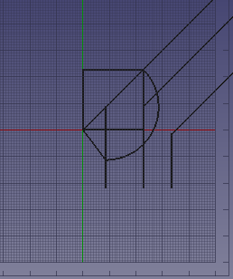
![]() Mirror
Mirror
select the joined line on the right hand side and key in m,i
select the middle line and snap to the the bottom point of the line
key in y to restrict to the y axsis
select the top point of the line
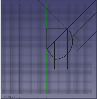
 Drafting
A Floorplan
In this tutorial you wil draft a 2d floorplan of the using an existing one as reference
WIP steps floorplan
importing the site
select file> import >navigate to the site folder and select the file named_____
the importer dialogue apears
*if not request change in drop down menu; edit preferences
use the c++ importer
use the options;
import
“texts and dimensions’,
‘simple part shapes’
‘treat ellipses and splines as poly lines’,
‘set scale factor as units from that file to mm. If the file is in meters set it to 1000 if the file is in mm set the factor to 1.’
Drafting a floorplan
open the file_____
select construction mode![]()
key in py and select the
following points in order ; A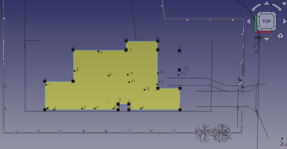 ,B,C,D,E,F,G,H,J,K,L,M,N,O,P,A
to form a closed polygon (PY1)
k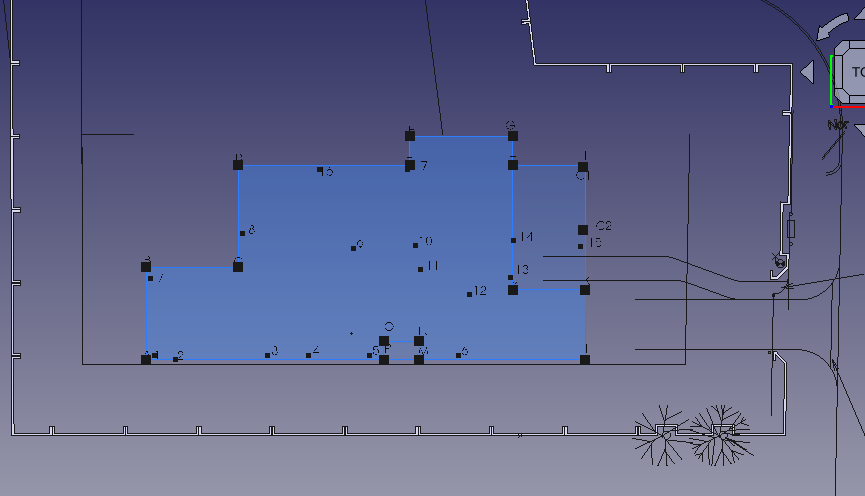 ey
in py and select the following points in order; A, B, C, D, E, F, G,
H, I, K,L, A
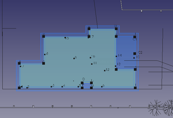
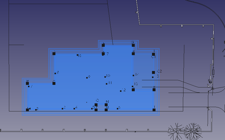
select PY 1 sin the combo view under construction
key in o,s, move the cursor inside the shape and key in 220 mm in the tasks tab that opened this create poly line py3
s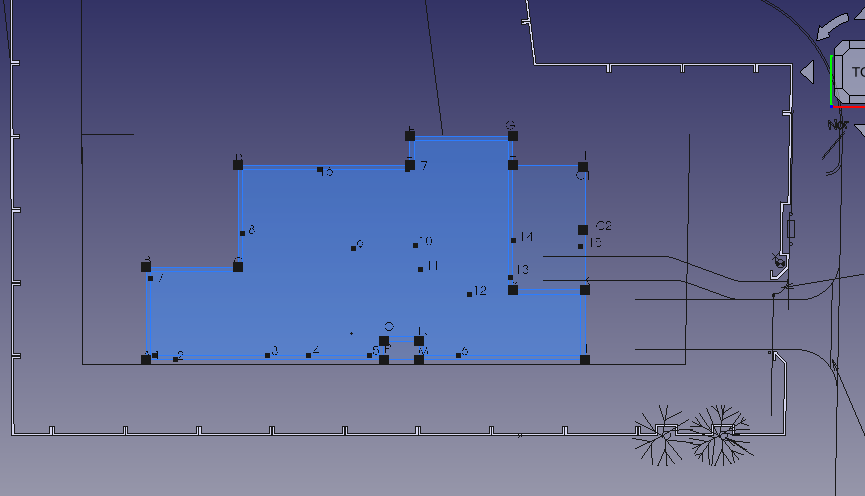 elect
py 2 and key in o,s, move the cursor out side of the poly line and
key in 300 mm
select py 4 and key in o,s. Move the cursor outside of the shape, Key in 300 mm in the task tab on the right of the screen
Rooms and walls
in the model view select the polylines you made and set make face to false
press shift r while the view space is at wc/shower
press shift E and select the object
key in m,v and click on the left most corner
move this
corner to point 0 ; key in mv, select the point and then select the
destination point.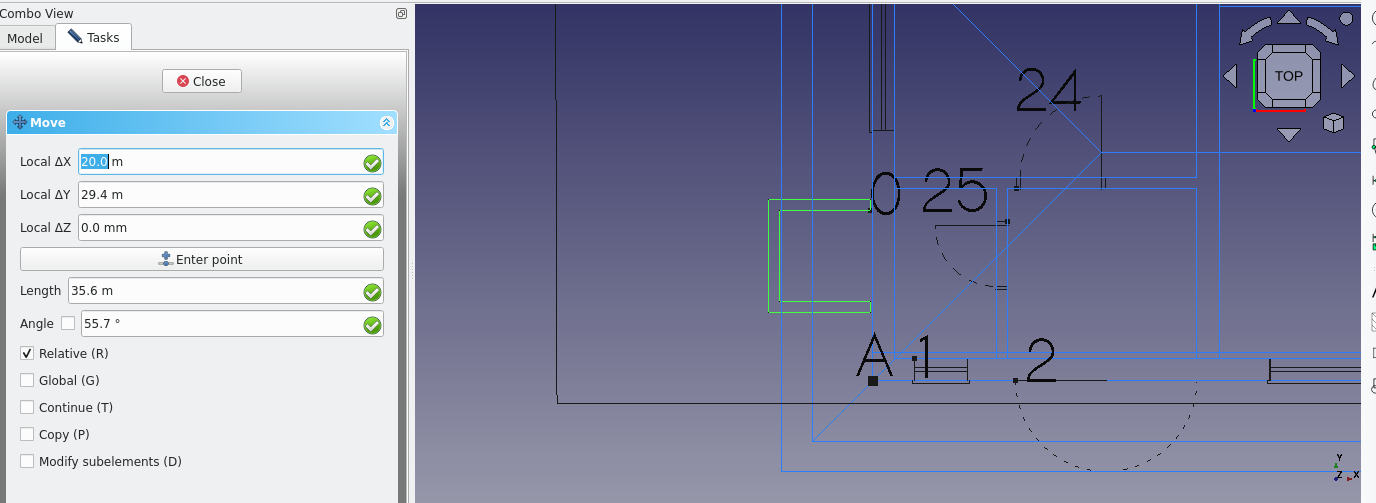
key in r,e and create reactangles of the following dimmensions (each representing the size of a room.
WC /shower 1010 by 1690 and 1880 by 1690
M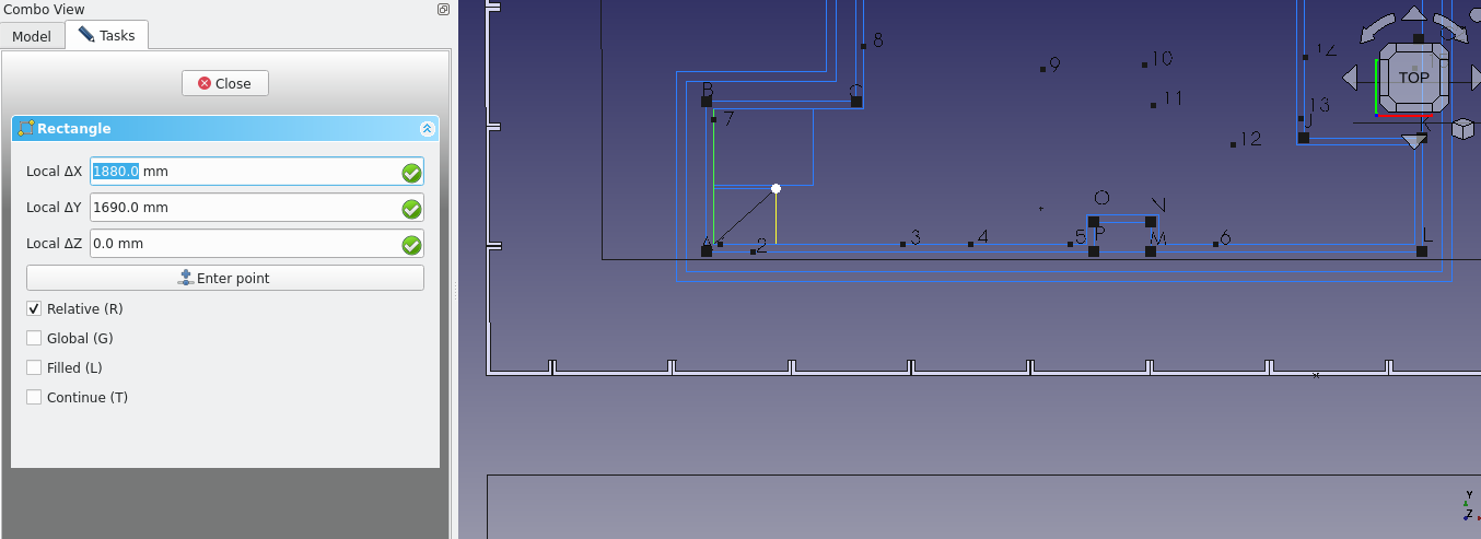 aid’s
room ; 2300 by 3000 ( select the rectangle and key in ‘m,v’
this rectangle key in x and type in 110 mm and press the enter key
B edroom
is 3000 by 3500 move this rectangle to the right of the maids room
by 220. The walk in cupboard is 2400 by 600 and 600 by 490. move
this rectangle by 110 mm to the right.
The Bathroom is 1800 by 2400. Key in “re” enter the dimmensions and press enter. Move the rectangle 110 mm to the right; select the rectangle and key in ‘m,v’ select the bottom left corner and key in x, then enter 110 mm and hit enter.
Bedroom
2 is 3000 by 3500 the walk in cupboardis 490 by 600 and 2400 by 600.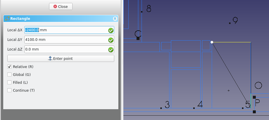 Be sure to move the 490 by 600 rectangle 110 mm to the right.
The
kitchen consists of 4000 3200 and 1945 by 900.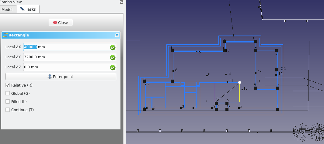 the first rectangle should be moved to the right by 110 keu in mv
and select the recangle, key in x and then 110 and press enter.
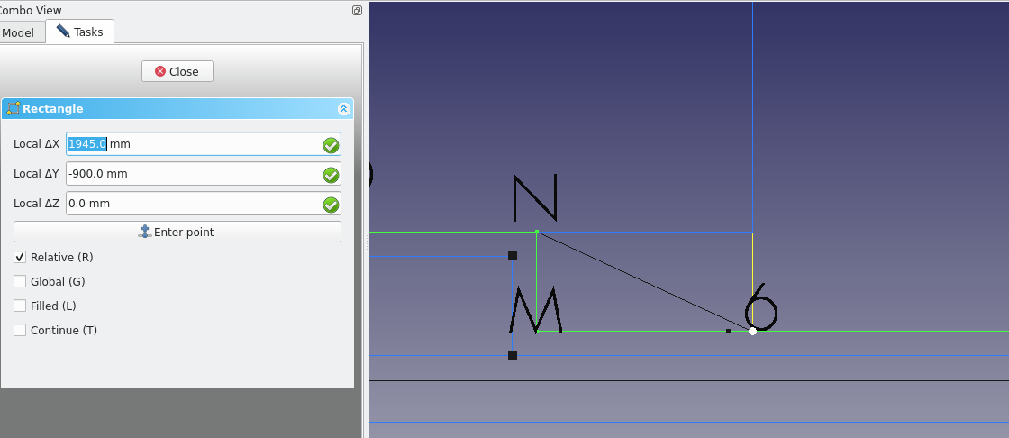 The
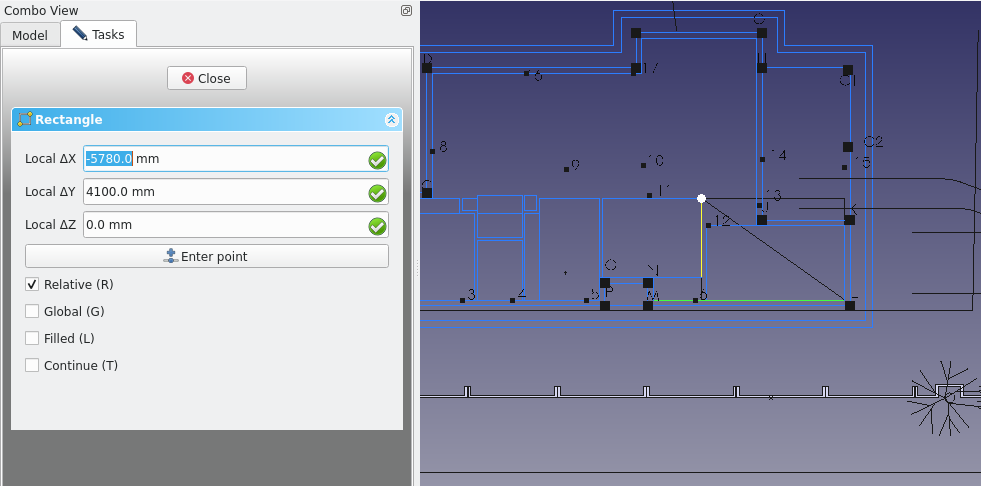
garage is 5560 by 3000, key in re to create the rectangle and select
the starting point diagonal to I (next to the kitchen).
 The
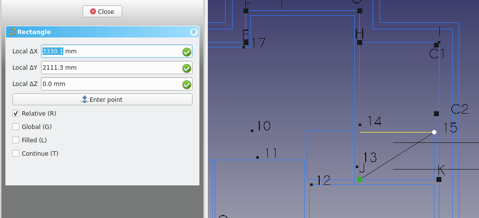
Porch is 3330 by 2111 and should be 110 mm above the garage
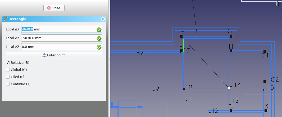
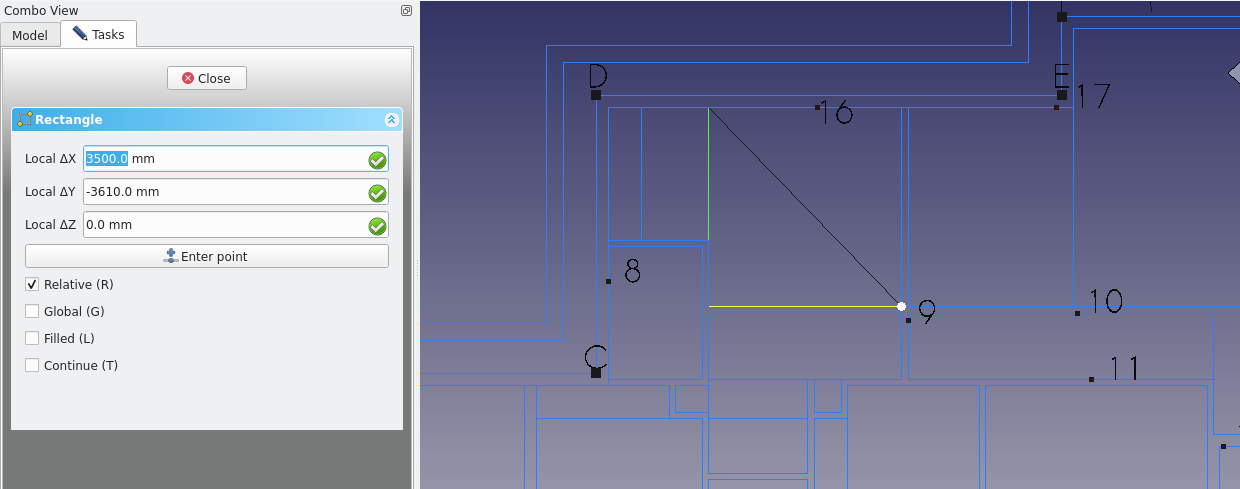
The sitting room is 4640 by 5030 and should be placed at the point diagonal to G.( 220 in the x direction and 220 in the y direction from point G).
 The
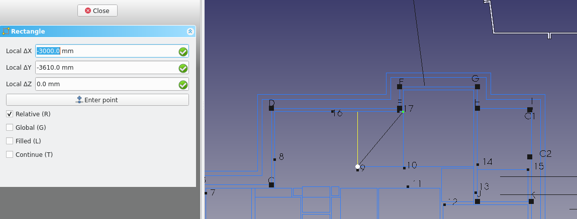
dining room is 3000 by 3610 and should be placed to the left of the
sitting room
 The
Master bed room 3500 by 3610 and 1810 2410
the En suite is 1700 by 2400
The Passage is;1800 by 990 (1800 710) (3500 1200) (5520.0 1200) and should be moved 110 mm from the ensuit
The lobby is (2120 by 2190)

Window and door placement
at point 0 place block
at point 1 place w5
at point 2 place d14
at point 3 place w4
at point 5 place w2
70 mm from point l place d5
at point 6 place w1
at point 7 place w6
at point 9 place w7
at point 10 place d6
at point 11 place d4
at point 12 place d2
at point 13 place d1
at point 14 place d7
at point 16 place w8
at point 17 place w9
at point 18 place w10
at point 19 place d10
at point 20 place d9
at point 21 place d12
at point 22 place d13
at point 23 place d11
at point 24 place d16
at point 25 place d15
at point 26 place place d3
Rooflinesmv
doors and windows
insert the window and door blocks as shown
lenghth 2000 mm , sill is 30 mm, ( 90,li 40, 90)
1996
2489
2480
15110
lm