05
Tutorial 05 (was 02 Part c): Creating 2D Geometry
Tutorial 3 Part ag: Creating A Floor Plan
Step 1: downloading/saving opening an existing file
Task 1
Download/Save and open the file named ‘floorplanbase’
Steps
Download this file floorplanbase and save to your preferred folder
Start FreeCAD
Navigate to your preferred folder
Open the downloaded file in your preferred folder (by default this is normally a folder called downloads)
Notes on Construction mode and placing items in the construction folder
A note on construction mode and creating the building footprint
Select the Construction icon (
 );
selecting this icon toggles whether objects created are
construction lines (the shortcut for this tool is ’C’ then
‘M’)
);
selecting this icon toggles whether objects created are
construction lines (the shortcut for this tool is ’C’ then
‘M’)You can also turn Draft objects like lines or rectangles into construction lines by selecting them and then selecting the Add Construction icon (
 )
)Construction lines are useful for getting the general shape of an object before committing to a shape. They also don’t have to be deleted later when plotting
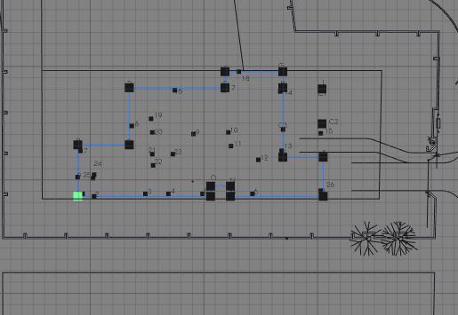
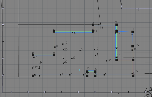
Step 2 : creating the building footprint
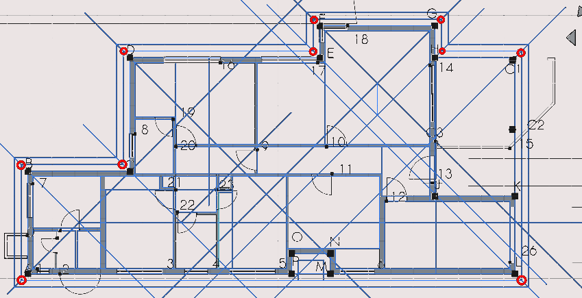
Press ‘P’ then ‘Y’ and select the following points in order; A, B, C, D, E, F, G, H, J, K, L, M, N, O, P, A to form a closed polygon (py1)
Navigate to Combo View>Tasks>Polyline
The >Tasks>Polyline dialogue will close when the Polyline forms a closed loop
Modifying the data of a Polyline
Navigate to Combo View Model Data
Select the Polyline again and press F2 or option-click the item and select rename on the menu that appears, to rename it
Key in ‘py1’
Note the Polyline will be in a group titled construction under Combo View>Model
Step 3: creating the roof and slab outlines
Creating the slab line with Polylines
Press 'P 'then 'Y' and select the following points in order; A, B, C, D, E, F, G, H, I, K, L, A
Select py1 in the Combo View under construction
Press 'O' then 'S' or select the offset tool icon (
 ),
move the cursor inside the shape and key in 220 mm in Combo
View>Tasks
),
move the cursor inside the shape and key in 220 mm in Combo
View>Tasks
Rename the line to py3
Creating the roof line with Polylines
Press 'P' then 'Y' and select the following points in order; A, B, C, D, E, F, G, H, I, K,L, A
Select py1 in the Combo View under construction
Press 'O' then 'S', move the cursor inside the shape and key in 220 mm in Combo View>Tasks
Navigate to Combo View>Tasks and select the newly created Polyline. Press F2 to rename the item
Rename the line to py3
Select py3 and press 'O' then 'S'. Move the cursor outside of the shape, key in 300 mm in the task tab on the right of the screen and press ‘Enter‘
Select the new line and rename it as py4
Select Polyline py4 and press 'O' then 'S' enter 300 mm and press 'Enter' (make sure to hover the mouse outside of the boundaries of the selected line)
Combo View>Model
Select the newly created Polyline in the Combo View
Option click the Polyline and select rename
Type in ‘py5’
What are Blocks?
Blocks are a combination of Draft or Arch objects that do not touch or form closed loops with each other
Think of them as a less flexible folder containing multiple objects. Blocks are created by selecting objects and selecting the upgrade icon (
 )
(assuming they don't form a closed loop or intersect with each
other)
)
(assuming they don't form a closed loop or intersect with each
other)
Moving and copying an existing Block
Select the block object labelled 'wc/shower'
Press 'M' then 'V' or select the Move tool icon(
 )
and select the left-most corner
)
and select the left-most corner
Step 4: creating construction lines for the inner walls
Press 'R' then 'E' and create Rectangles of the following dimensions (each representing the size of a room). Navigate and pan to the points using your preferred navigation style
Press 'R' then 'E' or select the Rectangle icon (
 )
with Point Snap on to ensure the Rectangle starts at the same
exact point indicated below
)
with Point Snap on to ensure the Rectangle starts at the same
exact point indicated below
Creating a rectangle as a base for the maid quarters
Select the corner as shown in the image above
Navigate to Combo View>Model and under Rectangle enter the following;
For Local ΔX input 3000 mm
For Local ΔY input 2300 mm
Leave Local ΔZ input as 0 mm
Select enter point to confirm each option
Creating a Rectangle as a base for the maid quarters bathroom (part A)
Press 'R' then 'E' or select the Rectangle icon (
)
Select the corner shown above
Navigate to Combo View>Model and under Rectangle enter the following:
For Local ΔX enter 1880 mm
For Local ΔY enter 1690 mm
Leave Local ΔZ as the default value
Select enter point to confirm the coordinates
Creating a Rectangle as a base for the maid quarters bathroom (part B)
Press 'R' then 'E' or select the Rectangle icon (
)
Select the corner highlighted above
Navigate to Combo View>Model under Rectangle enter the following:
For Local Δx enter 1010 mm
For Local Δy enter 1690 mm
Leave Local ΔZ as default
Press 'Enter' confirming each option or select enter point when done entering
Select the newly created Rectangle
Press 'M' then 'V' or select the Move tool icon (
)
Select the corner previously selected
Press 'X' (to restrict to x axis)
For Local ΔX enter 110 mm (note the greying out of the Local ΔY fields and Local ΔZ this means the object is limited to movement in the x-axis direction) this is of course relative to the Working Plane)
Select enter point or press 'Enter' to accept each part of the coordinates
Creating a Rectangle as a base for the maid quarters kitchen
Press 'R' then 'E' or select the Rectangle icon (
)
Select the corner highlighted above
Navigate to Combo View>Model under Rectangle enter the following;
For Local ΔX enter 3000 mm
For Local ΔY enter 3500 mm
Leave Local ΔZ as default
Press 'Enter' or select enter point after you are done entering coordinates
Select the newly created Rectangle
Press 'M' then 'V' or select the Move tool icon (
)
Select the highlighted corner of the previously selected Rectangle
Press 'X' on the keyboard (to restrict to the x-axis)
For Local ΔX enter 220 mm
Select enter point to accept
Creating a Rectangle as a base for the storage rooms
Press 'R' then 'E' or select the Rectangle icon (
)
Select the highlighted corner shown above
Navigate to Combo View>Model and under Rectangle enter the following:
For Local ΔX enter 2400 mm
For Local ΔY enter 600mm
Leave Local ΔZ as default
Select enter point
Select the newly created Rectangle
Press 'M' then 'V' or select the Move tool icon (
)
Select the corner previously selected
Press 'X' (to restrict to x axis)
For Local ΔX enter 220 mm
Select enter point or press ‘Enter’
Creating a Rectangle as a base for storage room 1 (part A)
Press 'R' then 'E' or select the Rectangle icon (
)
Select the corner highlighted above
Navigate to Combo View>Model and under Rectangle enter the following;
For Local ΔX enter 490 mm
For Local ΔY enter -600mm
Leave Local ΔZ as default
Select enter point
Select the newly created Rectangle
Press 'M' then 'V' or select the Move tool icon (
)
Select the corner previously selected
For Local ΔX enter 220 mm
For Local ΔY enter -110 mm
Select enter point or press 'Enter'
Creating a Rectangle as a base for storage room 1 (part B)
Press 'R' then 'E' or select the Rectangle icon (
)Navigate to Combo View>Model and under Rectangle enter the following:
For Local ΔX enter 1800 mm
For Local ΔY enter 2400 mm
Leave Local ΔZ as default
Press 'Enter' confirming each option or select enter point
Select the newly created Rectangle
Press 'M' then 'V' or select the Move tool icon (
)
Select the highlighted corner of the previously selected Rectangle
Press 'X' (to restrict to x axis)
For Local ΔX enter 110 mm
Select enter point or press 'Enter'
Creating a Rectangle as a base for the bathroom
Press 'R' then 'E' or select the Rectangle icon (
)
Select the corner highlighted in the image above
Navigate to Combo View>Model under Rectangle enter the following:
For Local ΔX enter 1800 mm
For Local ΔY enter 990 mm
Leave Local ΔZ as default
Select enter point
Select the Rectangle just created
Press 'M' then 'V' or select the Move tool icon (
)
Select the corner previously selected
Press 'Y' (to restrict to the y-axis)
For Local ΔY enter 110 mm
Select enter point or press 'Enter'
Creating a Rectangle as a base for the bathroom passage (Part A)
Press 'R' then 'E' or select the Rectangle icon (
)
Select the corner highlighted in the image above
Navigate to Combo View>Model and under Rectangle enter the following:
For Local ΔX enter 1800 mm
For Local ΔY enter 990 mm
Leave Local ΔZ as default
Select enter point
Select the newly created Rectangle
Press 'M' then 'V' or select the Move tool icon (
)
Select the corner previously selected
Press 'Y' (to restrict to y axis)
For Local ΔY enter 110 mm
Select enter point
Creating a Rectangle as a base for the bathroom passage (part B)
Press 'R' then 'E' or select the Rectangle icon (
)
Select the corner highlighted in the image above
Navigate to Combo View>Model and under Rectangle and enter the following:
For Local ΔX enter 600 mm
For Local ΔY enter 1800 mm
Leave Local ΔZ as default
Select enter point
Creating a Rectangle as a base for storage room 2 (part A)
Press 'R' then 'E' or select the Rectangle icon (
)
Select the corner highlighted in the image above
Navigate to Combo View>Model and under Rectangle enter the following;
For Local ΔX enter 600 mm
For Local ΔY enter 600 mm
Leave Local ΔZ as default
Press 'Enter' confirming each option or select enter point
Select the Rectangle you just created
Press 'M' then 'V' or select the Move tool icon (
)
Select the corner previously selected
Press 'X' (to restrict to x-axis)
For Local ΔX enter 110 mm
Select enter point or press 'Enter'
Creating a Rectangle as a base for storage room 2 (part B)
Press 'R' then 'E' or select the Rectangle icon (
)
Select the corner highlighted above navigate to Combo View>Tasks and under Rectangle enter the following;
For Local ΔX 600 mm
For Local ΔY enter -390 mm
Leave Local ΔZ as default
Press 'Enter' confirming each option or select enter point
Select the newly created Rectangle
Press 'M' then 'V' or select the Move tool icon (
)
Select the corner previously selected
Press 'X' (to restrict to the x-axis)
For Local ΔX enter 110 mm
Select enter point or press 'Enter’
Creating a rectangle as a base for the kitchen
Moving the Kitchen rectangle base
Press 'R' then 'E' or select the Rectangle icon (
)
Select the corner highlighted above
Navigate to Combo View>Model and under Rectangle enter the following;
For Local ΔX enter 4000 mm
For Local ΔY enter -3100 mm
Leave Local ΔZ as default
Press 'Enter' confirming each option or select enter point
Creating a Rectangle as a base for the garage
Press 'R' then 'E' or select the Rectangle icon (
)
Select the corner highlighted above
Navigate to Combo View>Model> and under Rectangle enter the following;
For Local ΔX enter -5560 mm
For Local ΔY enter -3000 mm
Leave Local ΔZ as default
Press 'Enter' confirming each option or select enter point
Creating a Rectangle as a base for the sitting room
Press 'R' then 'E' or select the Rectangle icon (
)
Select the corner highlighted above
For Local ΔX 5030 mm
For Local ΔY -4640 mm
Leave Local ΔZ as default
Press 'Enter' confirming each option or select enter point
Creating a Rectangle as a base for the dining room (part A)
Press 'R' then 'E' or select the Rectangle icon (
)
Select the corner highlighted
For Local ΔX enter -3610 mm
For Local ΔY enter -3000mm
Leave Local ΔZ as default
Press 'Enter' confirming each option or select enter point
Creating a Rectangle as a base for the dining room (part B)
Press ‘R’ then ‘E’ or select the rectangle icon (
 )
)Select the corner highlighted above
For ‘Local ΔX‘ enter -3610 mm
For ‘Local ΔY‘ enter -3000mm
Leave local Δz as default
Press 'Enter' confirming each option or select enter point
Creating a Rectangle as a base for the master bedroom (part A)
Press 'R' then 'E' or select the Rectangle icon (
)
Select the corner shown
For Local ΔX enter -3610 mm
For Local ΔY enter -3500 mm
For Local ΔZ enter 0 mm
Press 'Enter' confirming each option or select enter point
Creating a Rectangle base for the master bedroom (part B)
Press 'R' then 'E' or select the Rectangle icon (
)
Select the corner shown
For Local ΔX enter -3610 mm
For Local ΔY enter -3500 mm
For Local ΔZ enter 0 mm
Press 'Enter' confirming each option or select enter point
Creating a Rectangle base for the master bedroom (part B)
Press 'R' then 'E' or select the Rectangle icon (
)
Select the corner highlighted above
For Local ΔX enter 2410mm
For Local ΔY enter 1810mm
For Local ΔZ enter 0 mm
Press 'Enter' confirming each option or select enter point
Select the newly created Rectangle
Press 'M' then 'V' or select the Move tool icon (
)
Select the corner previously selected
Press 'Y' (to restrict to Y axis)
For Local ΔY enter 110 mm
Selected enter point or press 'Enter'
Creating a Rectangle as a base for the master bedroom (part C)

Press 'R' then 'E' or select the Rectangle icon (
)
Select the corner highlighted above
For Local ΔX enter 2400 mm
For Local ΔY enter 1920 mm
For Local ΔX enter 0 mm
Press 'Enter' confirming each option or select enter point
Select the newly created Rectangle
Press 'M' then 'V' or select the Move tool icon (
)
Select the corner previously selected
Press 'Y' (to restrict to y-axis)
For Local ΔY enter 110 mm
Selected enter point or press 'Enter'
Moving the Rectangle base for the master bedroom
file:///piw/data/cad/train/hartneyc/Modified%20scripts/html/fc-05/floorplan3.3.png
fix
Press 'R' then 'E' or select the Rectangle icon (
)
Select the corner highlighted
For Local ΔX enter 2400mm
For Local ΔY enter 600 mm
for Local ΔZ enter 0 mm
Press 'Enter' confirming each option or select enter point
Select the newly created Rectangle
Press 'M' then 'V' or select the Move tool icon (
)
Select the corner previously selected
Press 'Y' (to restrict to Y axis
For Local ΔY enter 110 mm
Selected enter point or press 'Enter'
Creating a Rectangle as a base for the main passage
Press 'R' then 'E' or select the Rectangle icon (
)
Select the corner highlighted above
For Local ΔX enter 2400mm
For Local ΔY enter 600 mm
For Local ΔZ enter 0 mm
Press 'Enter' confirming each option or select enter point
Select the newly created Rectangle
Press 'M' then 'V' or select the Move tool icon (
)
Select the corner previously selected
For Local ΔX enter 110 mm
For Local ΔY enter -100
Select enter point or press 'Enter' multiple times
Moving the square base for the main passage (part 1)
Press 'R' then 'E' or select the Rectangle icon (
)
Select the corner highlighted above
For Local ΔX enter 5520mm
For Local ΔY enter -1200 mm
For Local ΔZ enter 0 mm
Press 'Enter' confirming each option or select enter point
Select newly created rectangle
Press 'M' then 'V' or select the Move tool icon (
)
Press 'Enter' point or press 'Enter' multiple times
Moving the Rectangle base for the main passage (part 2)
Press 'R' then 'E' or select the Rectangle icon (
)
Select the corner highlighted
For Local ΔX enter 2190mm
For Local ΔY enter -2120mm
For Local ΔX enter 0 mm
Press 'Enter' confirming each option or select enter point
Step 5: placing ‘windows’ and ‘doors’
A note on how items are named in this tutorial
In 2D Drafting you create objects that represent views of actual objects as FreeCAD has actual objects which are categorised as walls, windows etc.
I will instead refer to their 2D representations with quotation marks to avoid confusion between Arch objects and Draft objects
Placing ‘window’ w5 at point 1
Navigate to the list of windows and doors
Select w5 as indicated above using Combo View>Model/blocks to display the list of objects in the drawing which you loaded at the beginning of tutorial 2
Make sure Point Snap(
 )
)
Press 'M' then 'V' or select the Move tool icon(
)
and select the object at the point shown above
Select the point labelled 1 (using Combo View>Model/points)
Next place ‘window’ w5 at point 2 following steps above
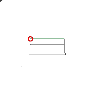
Placing ‘door’ d14
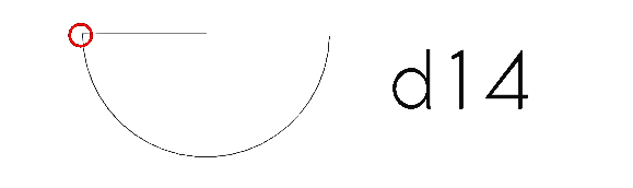
Select the block labelled d14 and press 'M' then 'V' or select the Move tool icon (
)
Select the point on d14 as shown in the image above
Navigate to Combo View>Tasks then select move, then select copy or press 'P'
Select point 2
Navigate back to the list of doors and windows using the preferred navigational style (Tutorial 01)
Placing ‘window’ w4 at point 3
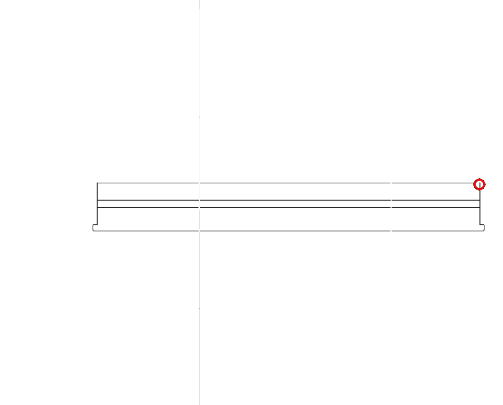
Select the block labelled w4
Press ‘M’ then ‘V’ or select the Move tool icon (
 )
)Select the point shown in the image above
Select the point 3
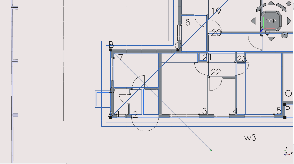
Placing ‘window’ w3 at point 4
Select w3
Press ‘M’ then ‘V’ or select the Move tool icon (
)Select the point on w3 shown above
Select point 4
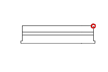
Placing ‘window’ w2 at point 5
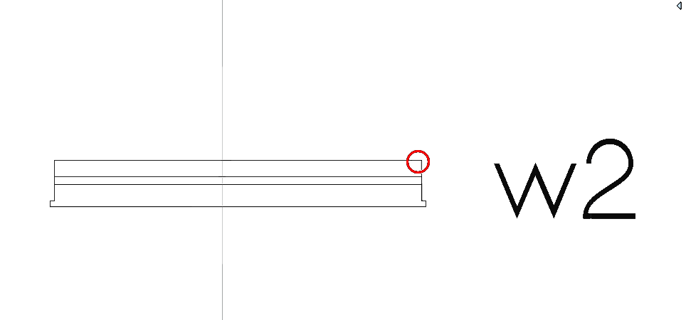
Improve image
Select w2
Press ‘M’ then ‘V’ or select the Move tool icon (
)Select the corner as shown in the image above
Select point 5
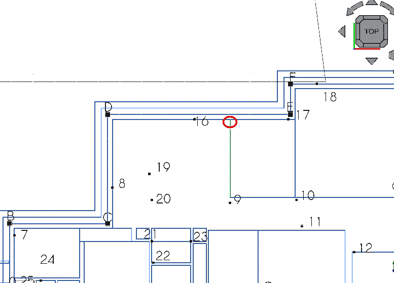
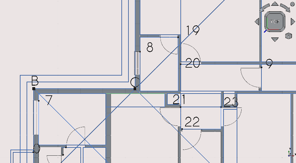
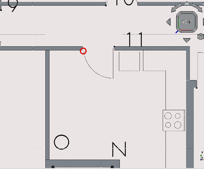
Place ‘window’ w6 at point 7
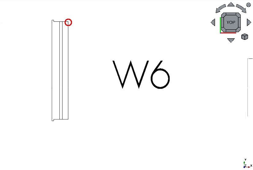
Select w6
Press ‘M’ then ‘V’ or select the Move tool icon (
)Select the point as shown in the image above
Select point 7
Placing ‘window’ w7 at point 8
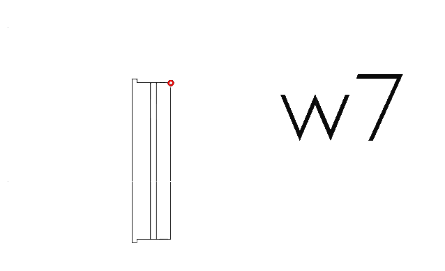
Select w7
Press ‘M’ then ‘V’ or select the Move tool icon (
)Select the point as shown in the image above
Select point 8
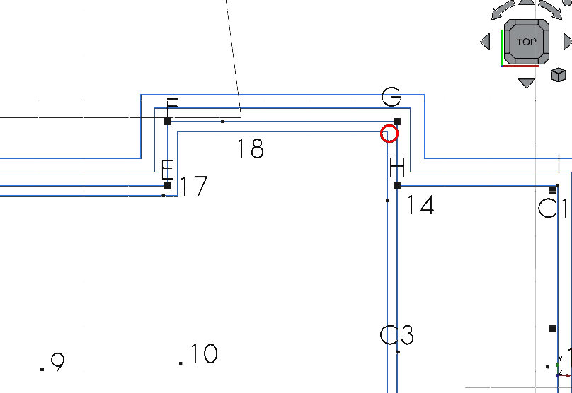
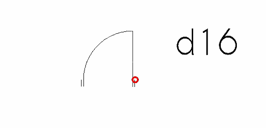
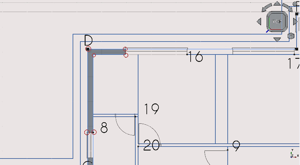
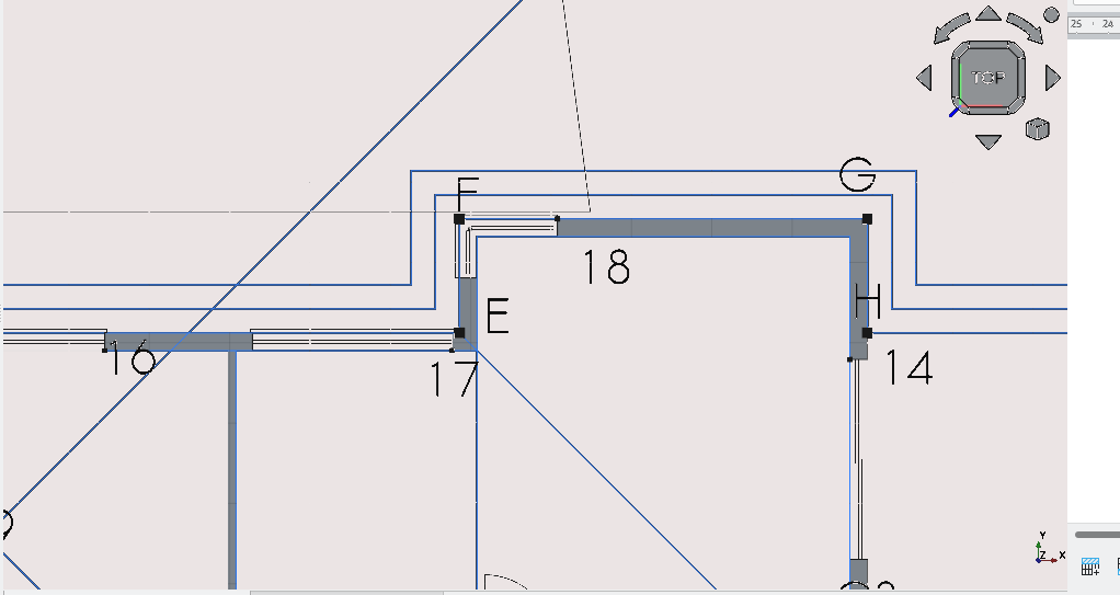
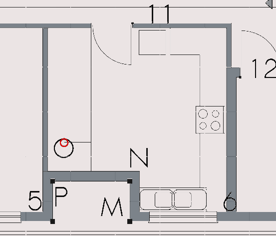
Placing ‘window’ w8 at point 16
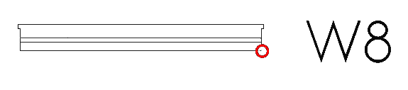
Select w8
Press ‘M’ then ‘V’ or select the Move tool icon (
)Select the point as shown in the image above
Select point 16
Placing ‘window’ w9 at point 17
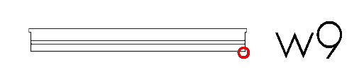
Select w9
Press ‘M’ then ‘V’ or select the Move tool icon (
)Select the point as shown in the image above
Select point 17
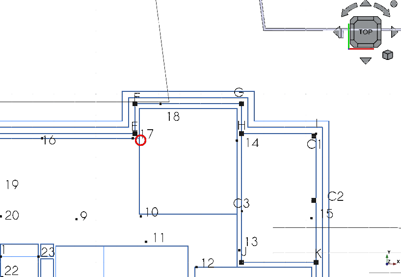
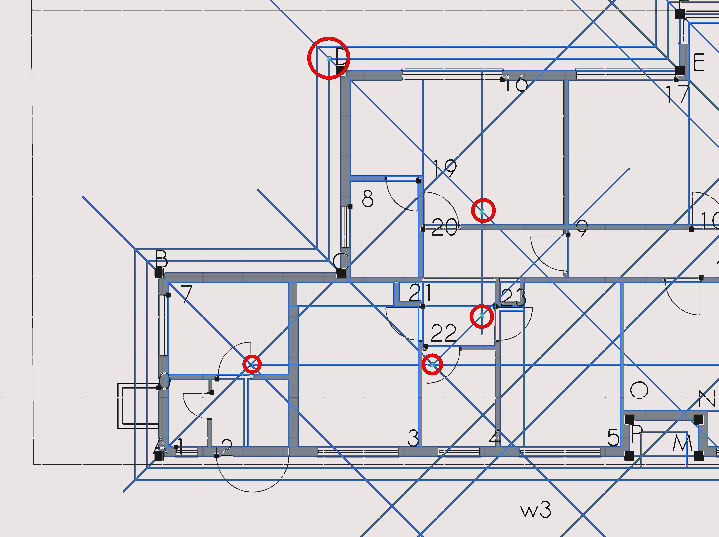
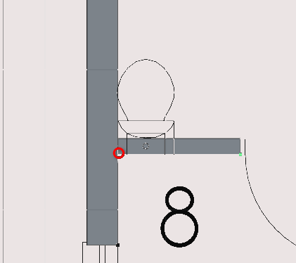
Placing ‘door’ d8 at point 9
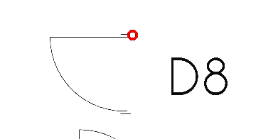
Select d8
Press ‘M’ then ‘V’ or select the Move tool icon (
)Select the point as shown in the image above
Select point 9
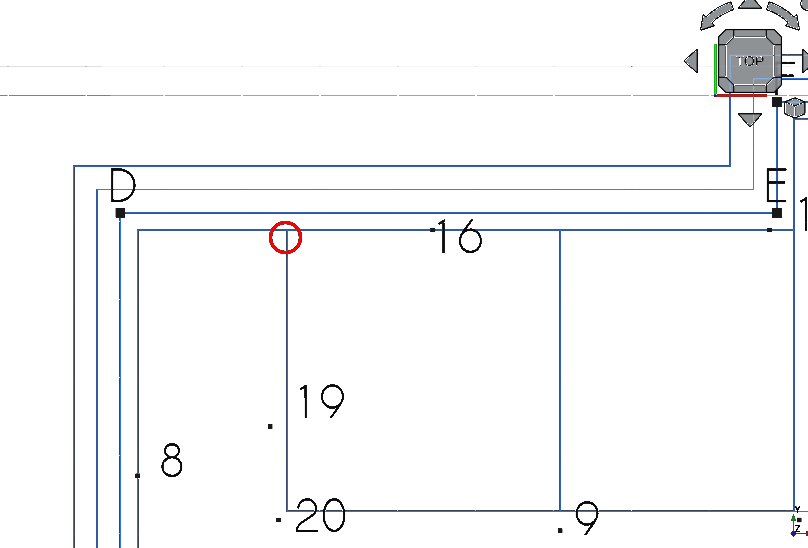
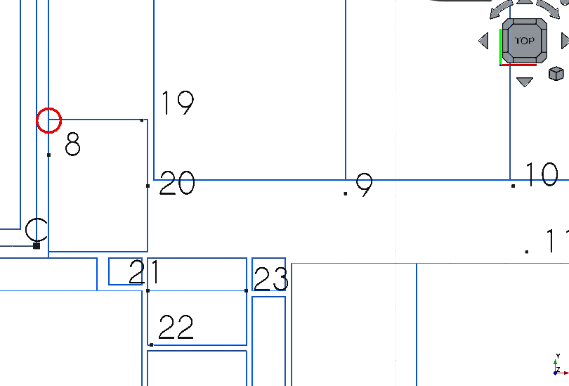
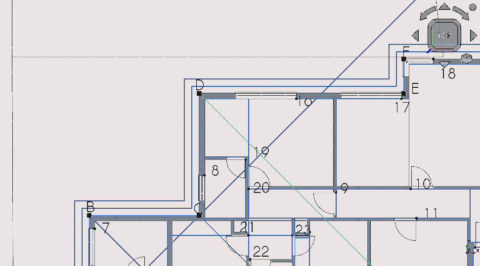
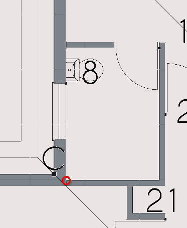
Placing ‘door’ d10 at point 19

Select d10
Press ‘M’ then ‘V’ or select the Move tool icon (
)Select the point as shown in the image above
Select point 19
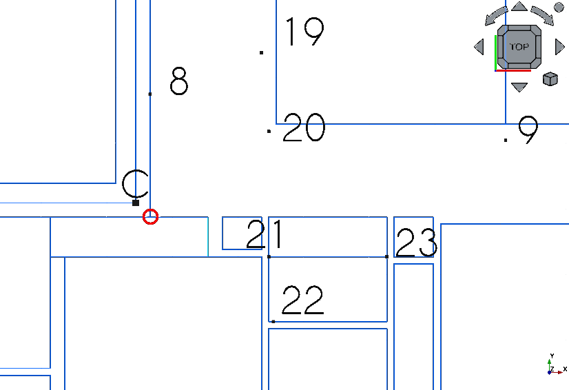
Placing ‘door’ d9 at point 20
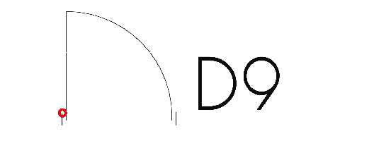
Select d9
Press ‘M’ then ‘V’ or select the Move tool icon (
)Select the point as shown in the image above
Select point 20
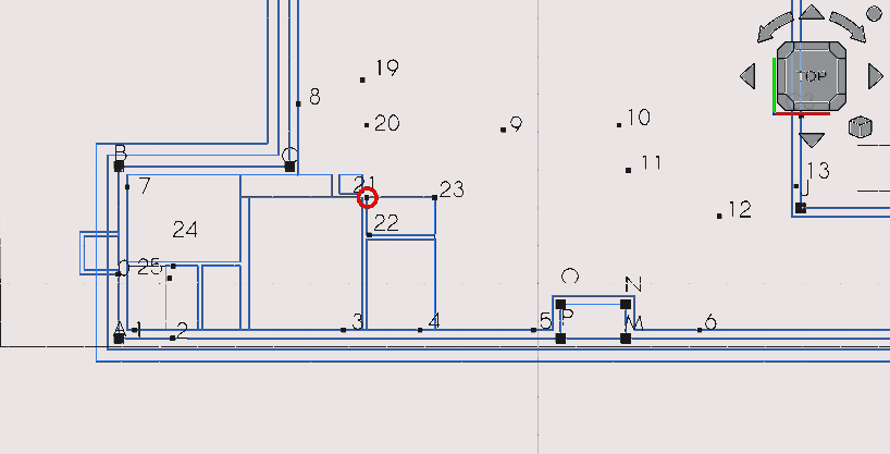
Placing ‘door’ d12 at point 21
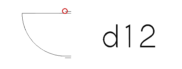
Select d12
Press ‘M’ then ‘V’ or select the Move tool icon (
)Select the point as shown in the image above
Select point 21
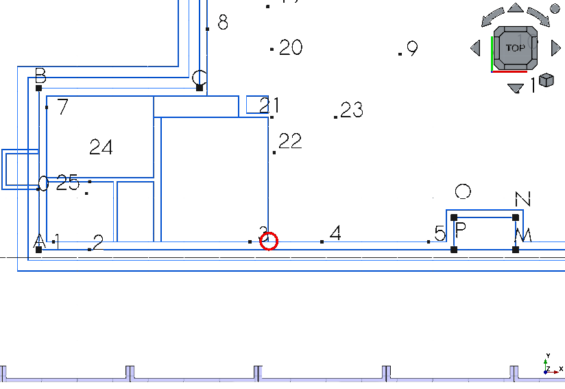
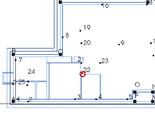
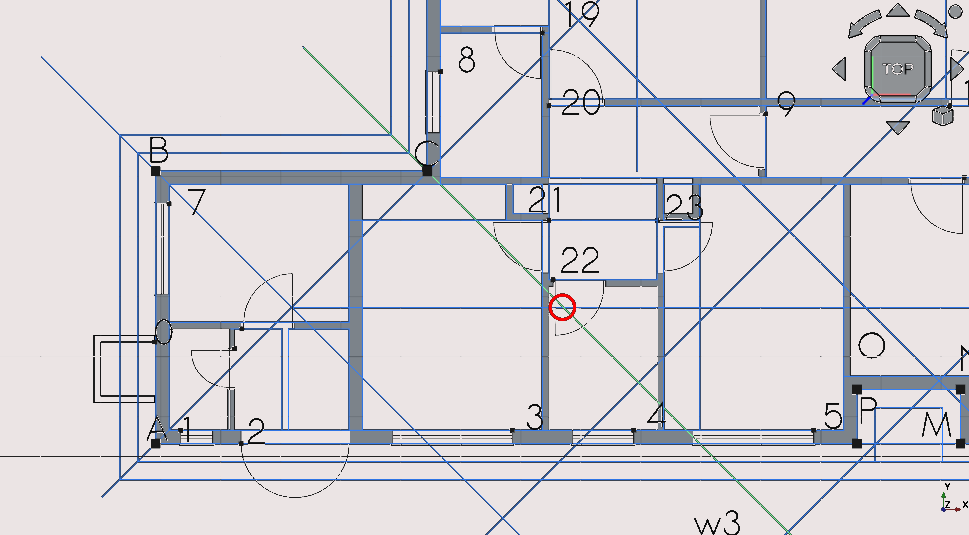
Placing ‘door’ d13 at point 22
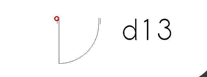
Select d13
Press ‘M’ then ‘V’ or select the Move tool icon (
)Select the point as shown in the image above
Select point 22
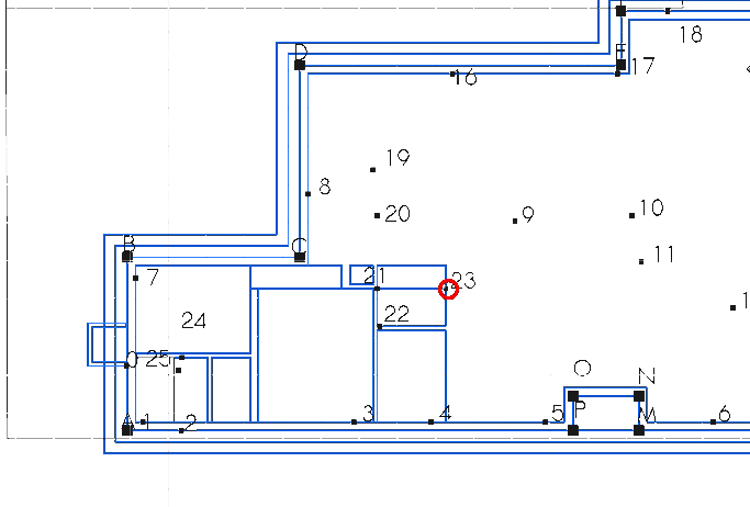
Placing ‘door’ d11 at point 23
Select d11
Press ‘M’ then ‘V’ or select the Move tool icon (
)Select the point as shown in the image above
Select point 23
Placing ‘door’ d2 at point 12
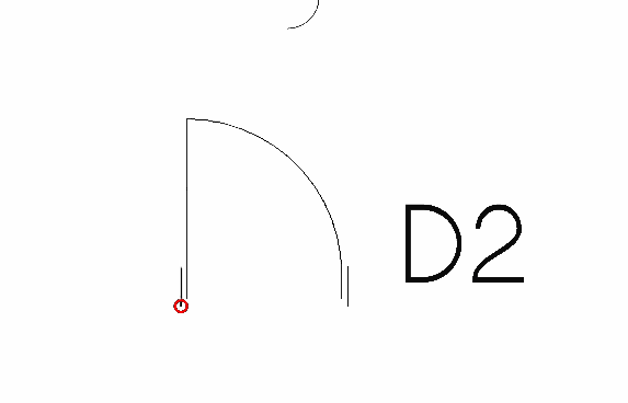
Select ‘d2’
Press ‘M’ then ‘V’ or select the Move tool icon (
)Select the point as shown in the image above
Select point 12
Placing ‘door’ d1 at point 13
Select d1
Press ‘M’ then ‘V’ or select the Move tool icon (
)Select the point as shown in the image above
Select point 13
Placing ‘door’ d7 at point 14
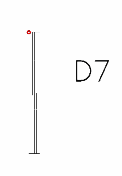
Select d7
Press ‘M’ then ‘V’ or select the Move tool icon (
)Select the point as shown in the image above
Select point 14
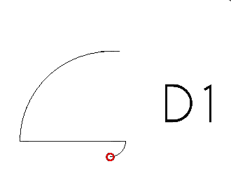
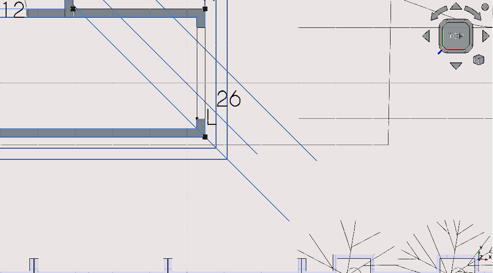
Placing ‘door’ d3 at point 26
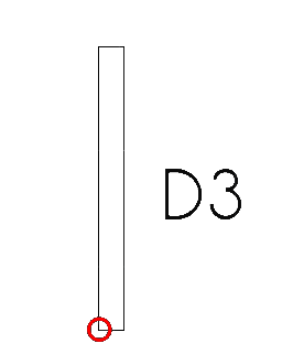
Select d3
Press ‘M’ then ‘V’ or select the Move tool icon (
)Select the point as shown in the image above
Select point 26
Step 6: creating the external ‘walls’
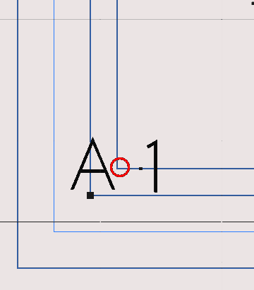
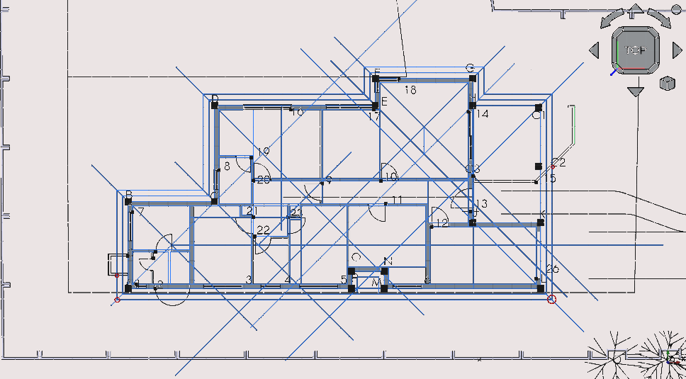
Creating outer ‘walls’ part 1 at point A

See task 3 of fc-02.html
Pan and zoom to point 'A' as above
Press 'P' then 'Y' or select the Polyline icon (
 );
using Snap Points select the vertexes as shown above (making
sure to create a closed loop), this creates a wire
);
using Snap Points select the vertexes as shown above (making
sure to create a closed loop), this creates a wire
Select the wire with your cursor in the Combo View menu press 'T' then 'G'; this navigates to objects selected in Combo View>Model (note: newly created items occur in order in Combo View>Model so by default the polyline will be at the bottom of the list)
Navigate to Combo View>Model>Data>Draft
Select the Make face property and pick true (this gives the created wire a fill which will be useful later for hatching)
Select the newly created wire
Option click with the cursor
Navigate to >Utilities>move to group>add new named group
Combo View>Tasks>Add group
Enter the group name 'walls' and select 'ok'
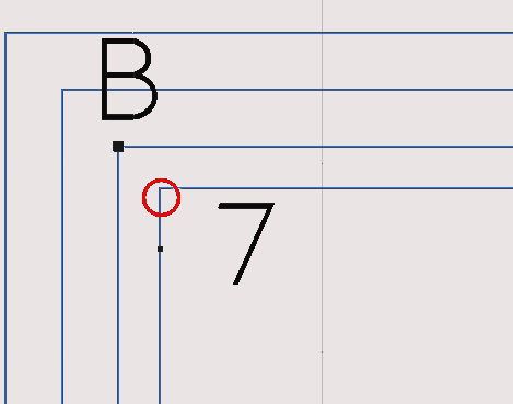
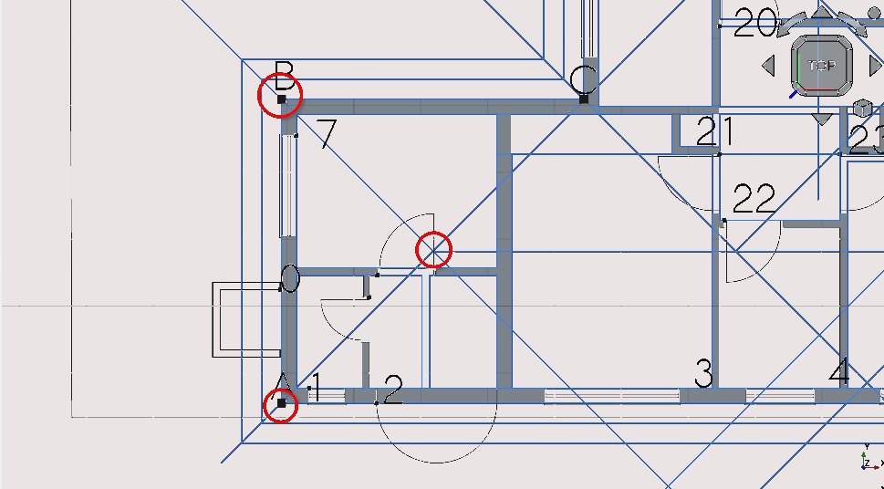
Creating outer 'walls' at points B and C (part 2)
Pan and zoom so that you can view both points; 'B' and 'C'
Press 'P' then 'Y' or select the Polyline icon (
)using Snap Points select the vertexes as shown above
Select the wire with your cursor (in the Combo View menu press 'T then 'G' this navigates to objects selected in the Combo View
Combo View>Model>Data>Draft
Select the Wire
Option click with the cursor
Utilities>move to group>Walls
Select Walls
If you have trouble selecting the polyline you can more easily select it in the Combo View
See task 3 of fc-02.html
Creating outer ‘walls’ at points C and D (part 3)
Pan and zoom so that you can view both points: 'C' and 'D'
Press 'P' then 'Y' or select the Polyline icon (
);
using Snap Points select the vertexes as shown above
Select the wire with your cursor (in the Combo View menu press 'T' then 'G' this navigates to objects selected in Combo View>Models
Navigate to Combo View>Model>Data>Draft
Select the newly created Wire
Option click with the cursor Navigate to >Utilities>move to group and select the group created called 'walls'
If you have trouble selecting the polyline you can more easily select it in the Combo View
Creating outer 'walls' at points D and E (part 4)
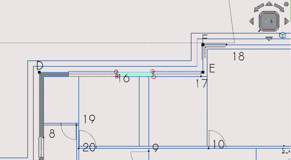
Pan and zoom so that you can view both points: 'D' and 'E'
Press 'P' then 'Y' or select the Polyline icon (
);
using Snap Points select the vertexes as shown above
Select the wire with your cursor (in the Combo View menu press 'T' then 'G' this navigates to objects selected in Combo View>Models
Navigate to Combo View>Model>Data>Draft
Select the newly created Wire
Option click with the cursor Navigate to utilities >move to group and select the group created called 'walls'
Creating outer 'walls' at points E and F (part 5)
Pan and zoom so that you can view both points: 'E' and 'F'
Press 'P then 'Y' or select the Polyline icon (
);
using Snap Points select the vertexes as shown above
Select the wire with your cursor (in the Combo View menu press 'T' then 'G' this navigates to objects selected in the Combo View)
Navigate to Combo View>Model>Data>Draft
Select the Wire
Option click with the cursor
Navigate to >Utilities>move to group
Select 'walls'
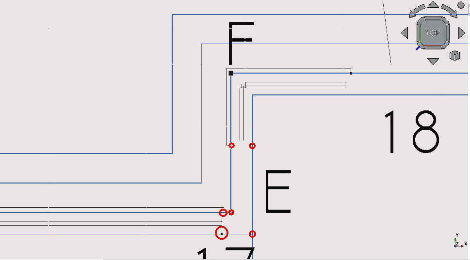
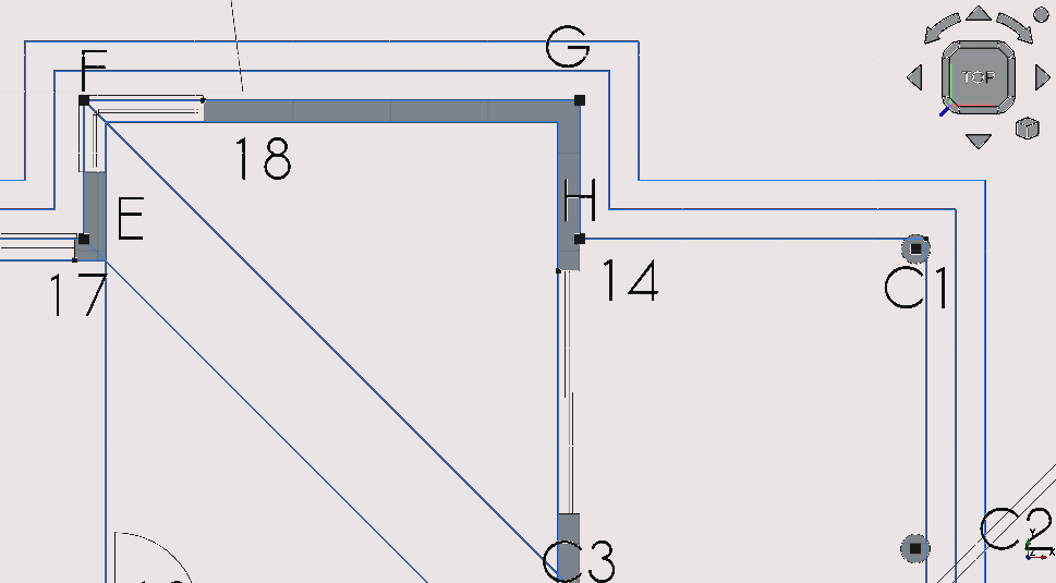
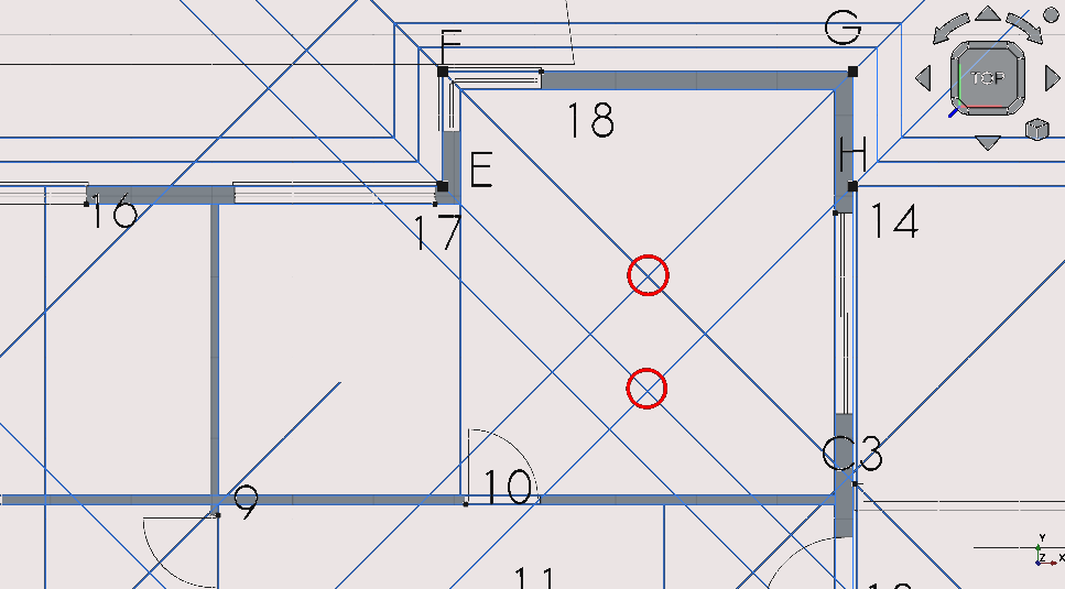
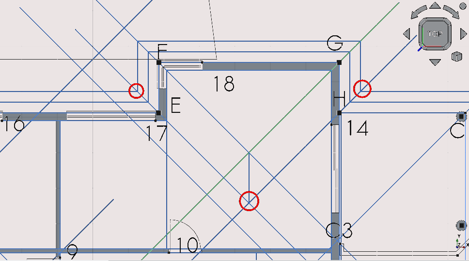
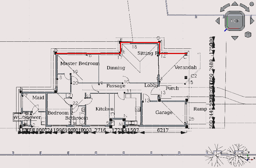
Creating outer 'walls' at points E, F, G and H (part 6)
Pan and zoom so that you can view points; E, F, G and H
Press 'P 'then 'Y' or select the Polyline icon (
);
using Snap Points select the vertexes as shown above
Select the wire with your cursor; in the Combo View menu press 'T' then 'G' this navigates to objects selected in the Combo View
Navigate to Combo View>Model>Data>Draft
Select the Wire
Option click with the cursor
Navigate to >Utilities>move to group
Select the group labelled 'walls'
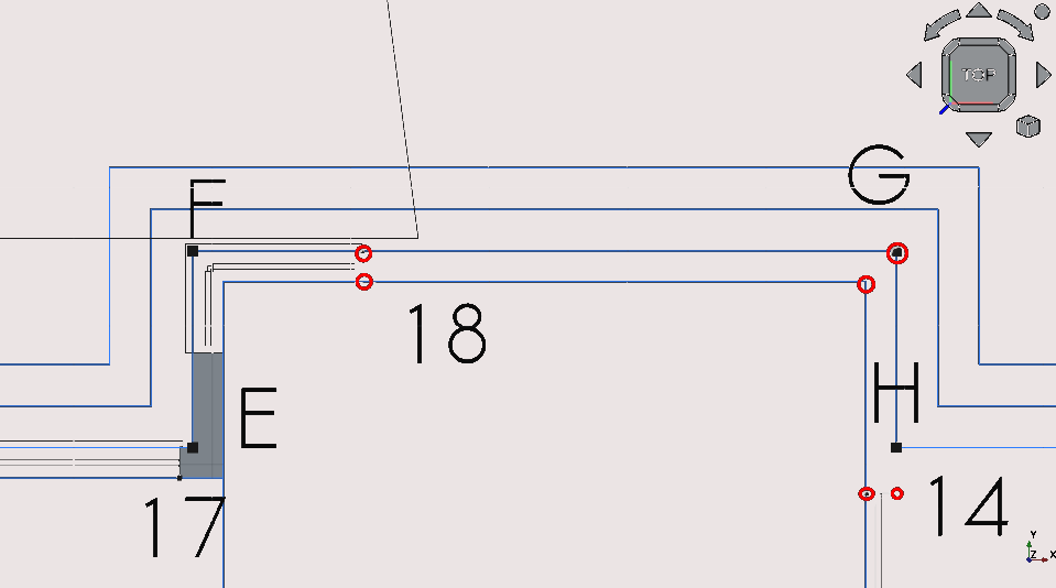
Creating outer 'walls' at point J (Part 7)
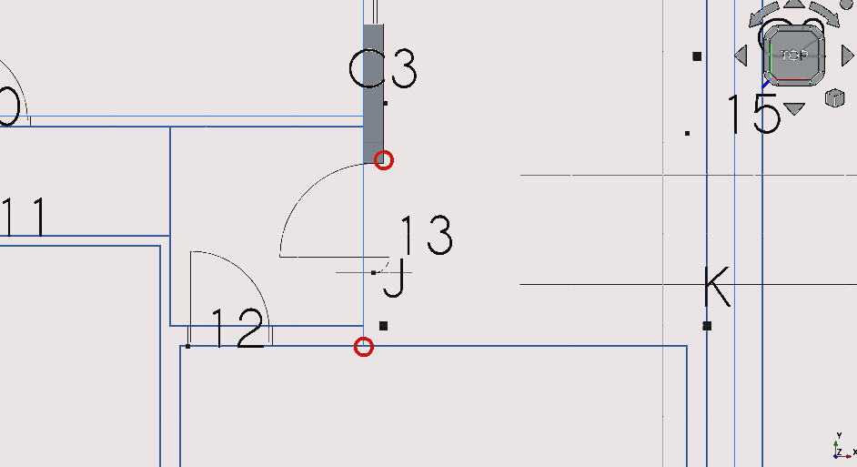
Pan and zoom so that you can view point J
Press 'R' then 'E' or select the Rectangle icon (
)
Select any two points circled above
Select the newly created Rectangle
Option click with the cursor
Navigate to >Utilities>move to group and select the group labelled 'walls'
Creating outer 'walls' at point J (Part 8)
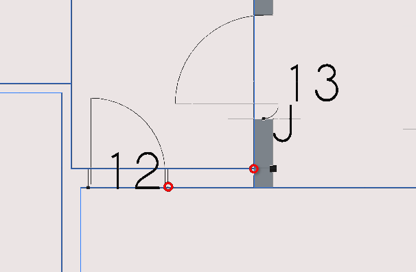
Pan and zoom so that you can view points 12 and 13
Press ‘R’ then ‘E’ or select the rectangle icon (
)Select the two points circled in the image above
Select the newly created rectangle
Navigate to Combo View>Model
Select the newly created with your cursor; in Combo View menu model press ‘T’ then ‘G’ this navigates to objects selected in the Combo View
Navigate to Combo View>Model>Data
Set Make face property to true
Select the newly created rectangle
Option click with the cursor
Navigate to >Utilities>move to group
Select the group labelled ‘walls’
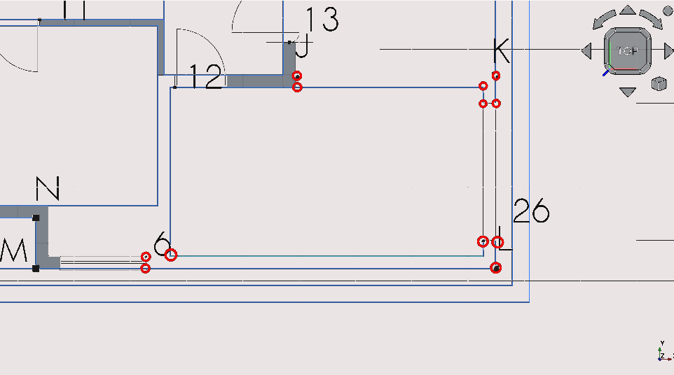
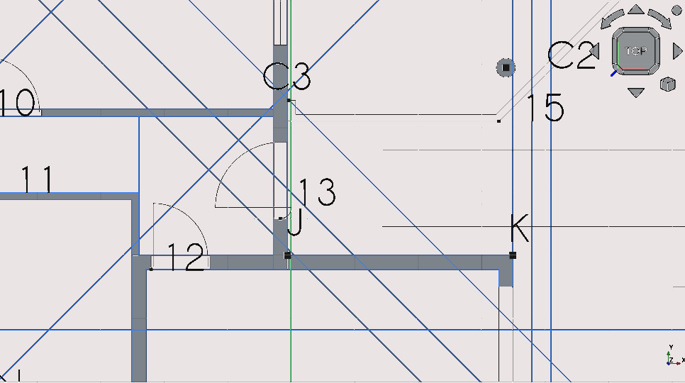
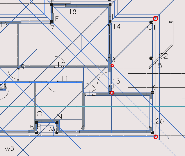
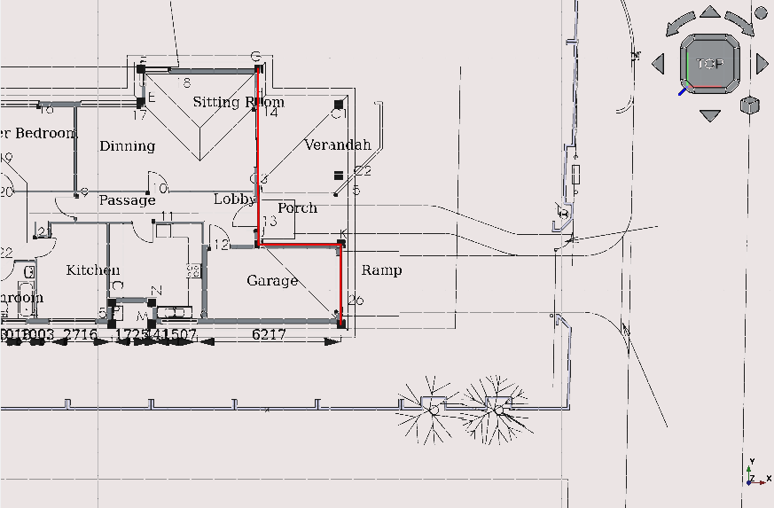
Creating external ‘walls’ at points J, 12, K, L and 6 (part 9)
Pan and zoom so that you can view points 12 and 13
Press 'R' then 'E' or select the Rectangle icon (
)
Select the two points circled in the image above
Select the newly created Rectangle
Navigate to Combo View>Model
Select the newly created Rectangle with your cursor; in Combo View>Model press 'T' then 'G' this navigates to objects selected in the Combo View
Navigate to Combo View>Model>Data
Set Make face property to true
Select the newly created Rectangle
Option click with the cursor
Navigate to >Utilities>move to group
Select the group labelled 'walls'
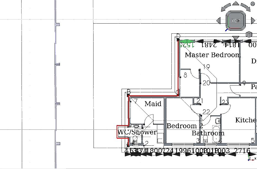
Creating outer ‘walls’ at points; J , N, M, 12 and 6 (part 10)
Pan and zoom so that you can view points 'J', 'N', 'M', '12' and '6'
Press 'P 'then 'Y' or select the Polyline icon (
)
Using Snap Points select the vertexes as shown above
To maintain a straight line you may restrict drawing a line by for example pressing 'X' to restrict the line in to the x-axis or 'Y' for the y- axis etc
Select the newly created wire
Navigate to Combo View>Data>Draft
Set the Make face property to true
Select the Wire
Option click with the cursor
Navigate to >Utilities>move to group
Select the group labelled 'walls'
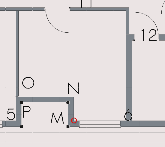
Creating outer ‘walls’ at points; 5 , P, O, N and M (part 11)
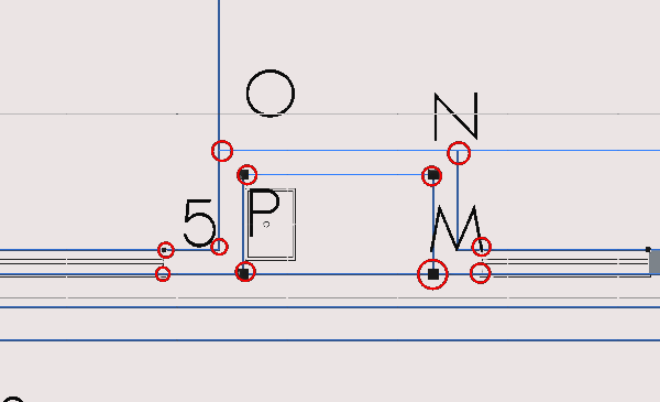
Pan and zoom so that you can view points; 5, P, O, N and M
Press 'P' then 'Y' or select the Polyline icon (
)
using Snap Points select the circled vertexes as shown above
Select the newly created wire
Navigate to Combo View>Data>Draft
Set the Make face property to true
Select the Wire
Option click with the cursor
Navigate to >Utilities>move to group
Select the group labelled 'walls'
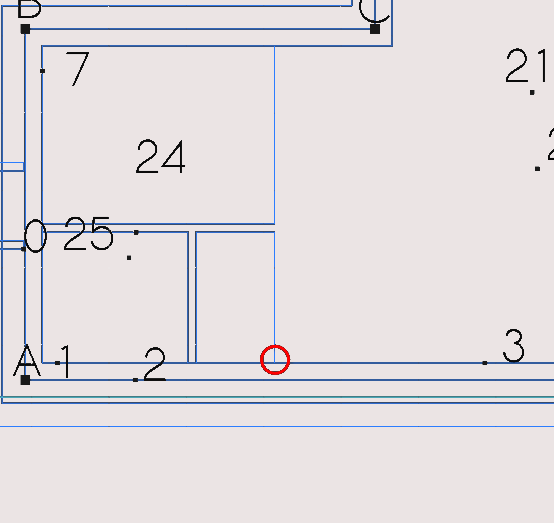
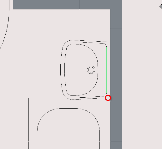
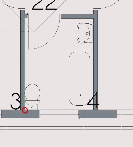
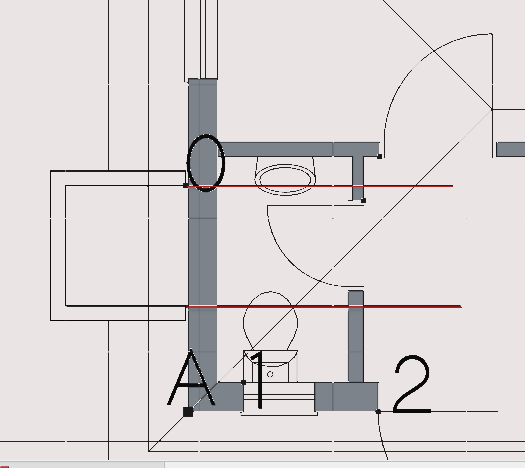
Creating outer ‘walls’ at point 4 (part 12)
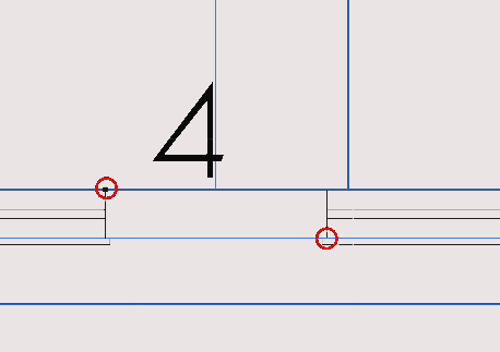
Pan and zoom so that you can view point 4
Press ‘R’ then ‘E’ or select the rectangle icon (
)Select the two points circled in the image above
Select the newly created rectangle
Navigate to Combo View>Model
Select the newly created with your cursor; in Combo View>Model press ‘T’ then ‘G’: this navigates to objects selected in the Combo View
Navigate to Combo View>Model>Data>
Set the Make face property to true
Select the newly created rectangle
Option click with the cursor
Navigate to >Utilities>move to group
Select the group labelled ‘walls’
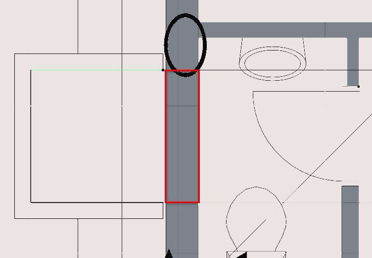
Creating outer ‘walls’ at point 3 (part 13)
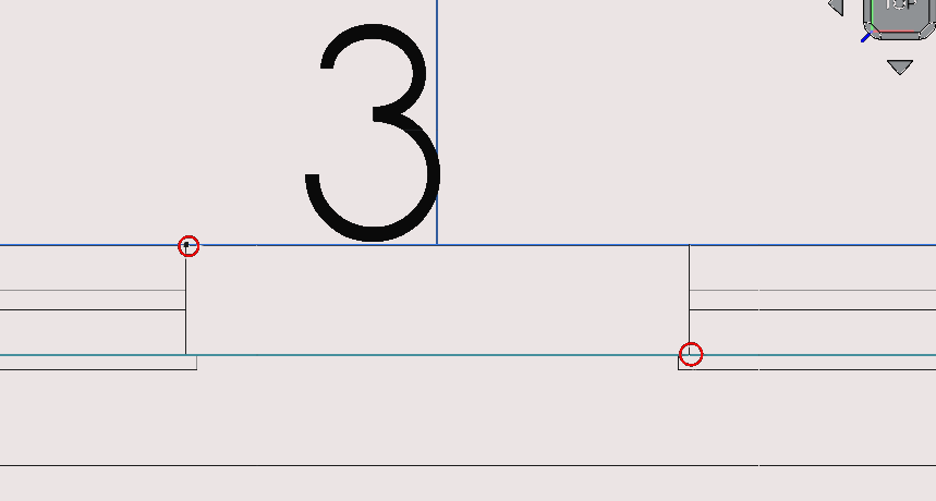
Pan and zoom so that you can view point 3
Press 'R' then 'E' or select the Rectangle icon (
)
Select the two points circled in the image above
Select the newly created Rectangle
Navigate to Combo View>Model
Select the newly created with your cursor; in Combo View>Model press 'T' then 'G': this navigates to objects selected in the Combo View
Navigate to Combo View>Model>Data>
Set the Make face property to true
Select the newly created Rectangle
Option click with the cursor
Navigate to >Utilities>move to group
Select the group labelled 'walls'
Creating outer ‘walls’ between d16 and w4 (part 14)
Pan and zoom so that you can view d16 and w4
Press 'R' then 'E' or select the Rectangle icon (
)
Select the two points circled in the image above
Select the newly created Rectangle
Navigate to Combo View>Model
Select the newly created with your cursor; in Combo View>Model press 'T' then 'G'
Navigate to Combo View>Model>Data>
Set the Make face property to true
Select the newly created Rectangle
Option click with the cursor
Navigate to >Utilities>move to group
Select the group labelled 'walls'
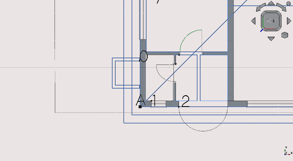
Creating outer ‘walls’ at points; 1 and 2 (part 15)
Pan and zoom so that you can view points 1 and 2
Press ‘R’ then ‘E’ or select the rectangle icon (
)Select the two points circled in the image above
Select the newly created rectangle
Navigate to Combo View>Model
Select the newly created with your cursor; in Combo View menu model press ‘T’ then ‘G’
Navigate to Combo View>Model>Data
Set the Make face property to true
Select the newly created rectangle
Option click with the cursor
Navigate to >Utilities>move to group
Select the group labelled ‘walls’
Step 7: creating inner ‘walls’
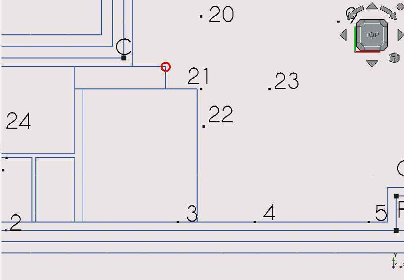
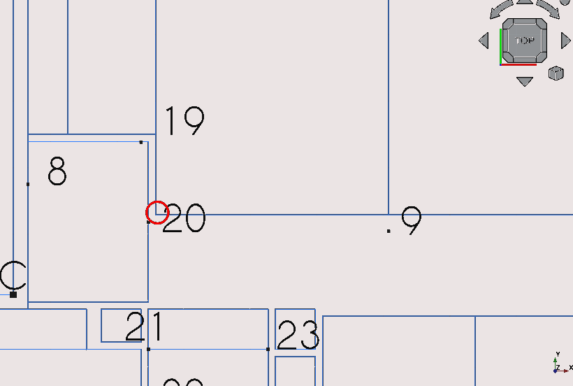
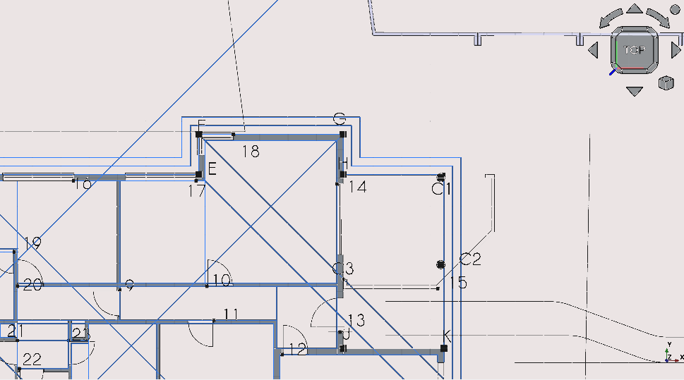
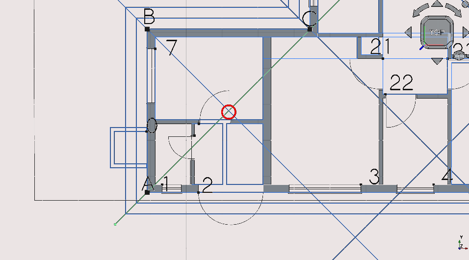
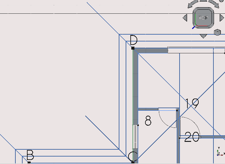
Creating inner ‘walls’ between points; 8 and 19 (part 1)
Pan and zoom so that you can view points; 8, 19, and 20
Press 'R' then 'E' or select the Rectangle icon (
)
Select the two points circled in the image above
Select the newly created Rectangle
Navigate to Combo View>Model
Select the newly created with your cursor; in Combo View>Model press 'T' then 'G’
Navigate to Combo View>Model>Data
Set the Make face property to true
Select the newly created Rectangle
Option click with the cursor
Navigate to >Utilities>move to group
Select the group labelled 'walls'
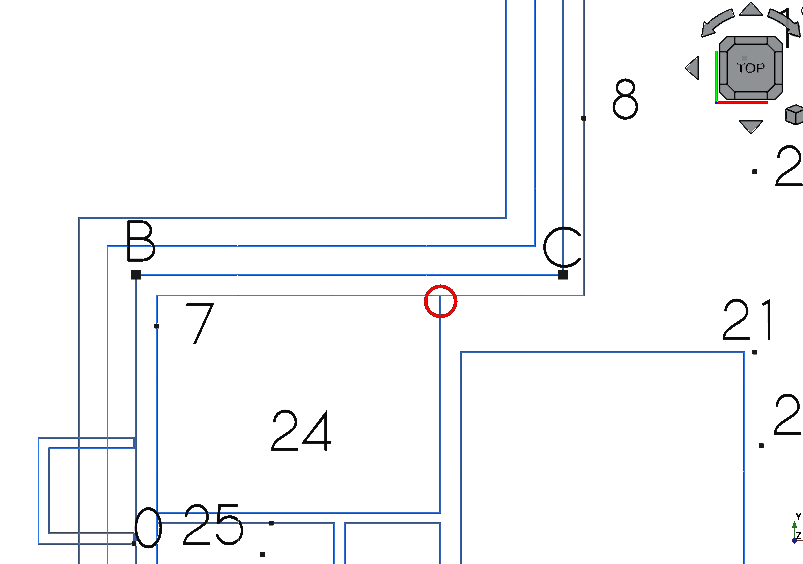
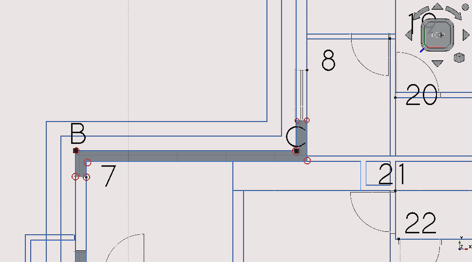
Creating ‘walls’ between points; C,8, 19, 20 (part 2)
Pan and zoom so that you can view points; C, 8, 19 and 20
Press ‘P’ then ‘Y’ or select the Polyline icon (
 );
using Snap Points select the circled vertexes as shown above
);
using Snap Points select the circled vertexes as shown aboveSelect the newly created wire
Navigate to Combo View>Data>Draft
Set the Make face property to true
Select the created Wire
Option click with the cursor
Navigate to >Utilities>move to group
Select the group labelled 'walls'
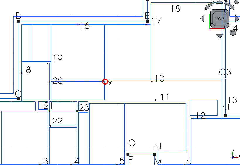
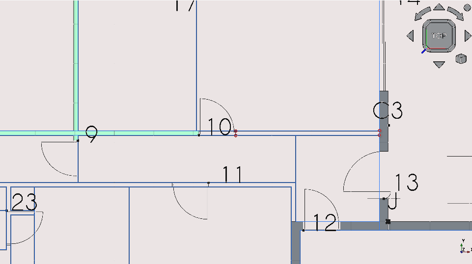
Creating ‘walls’ between points; C, 20, 16, 9 and 10 (part 3)
Pan and zoom so that you can view points; 20, 16, 9 and 10
Press 'P' then 'Y' or select the Polyline icon (
);
using Snap Points select the circled vertexes as shown above
Select the newly created wire
Navigate to Combo View>Data>Draft
Set the Make face property to true
Select the created Wire
Option click with the cursor
Navigate to >Utilities>move to group
Select the group labelled 'walls'
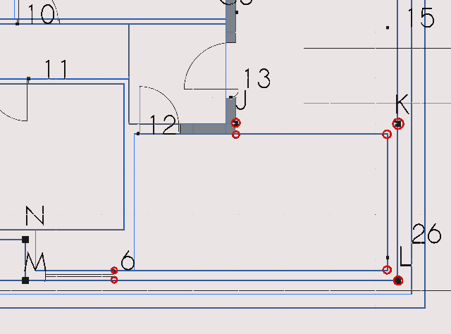
Creating ‘walls’ between points; 6, L, K, J and 12 (part 4)
Pan and zoom so that you can view points; 6, L, K, J and 12
Press 'P' then 'Y' or select the Polyline icon (
);
using Snap Points select the circled vertexes as shown above
Select the newly created wire
Navigate to Combo View>Data>Draft
Set the Make face property to true
Select the created Wire
Option click with the cursor
Navigate to >Utilities>move to group
Select the group labelled 'walls'
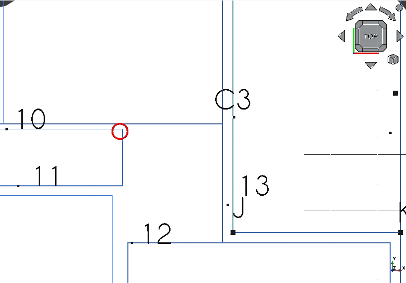
Creating ‘walls’ between points 10 and C3 (part 5)
Pan and zoom so that you can view points; 10 and C3
Press 'R' then 'E' or select the Rectangle icon (
)
Select the two points circled in the image above
Select the newly created Rectangle
Navigate to Combo View>Model
Select the newly created with your cursor; in Combo View>Model press 'T' then 'G'
Navigate to Combo View>Model>Data
Set the Make face property to true
Select the newly created Rectangle
Option click with the cursor
Navigate to >Utilities>move to group
Select the group labelled 'walls'
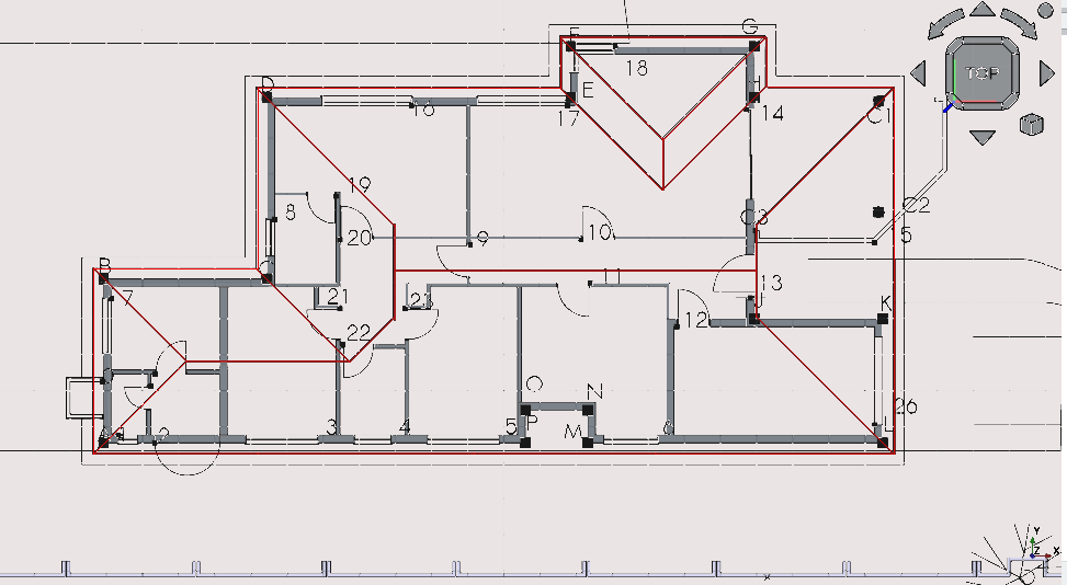
Going forward with creating walls (part 6)
By now you may have noticed a pattern in creating a ‘wall’ :
create a polyline, rectangle etc (any geometry with a closed loop)
Set the show face properties under Combo View>Data to true
Add the created geometry to the ‘walls’ group
From now the steps for this particular task (creation of ‘walls’ will be minimal)
Feel free to experiment with the different approaches of creating 2D geometry shown in the prior section on creating geometry
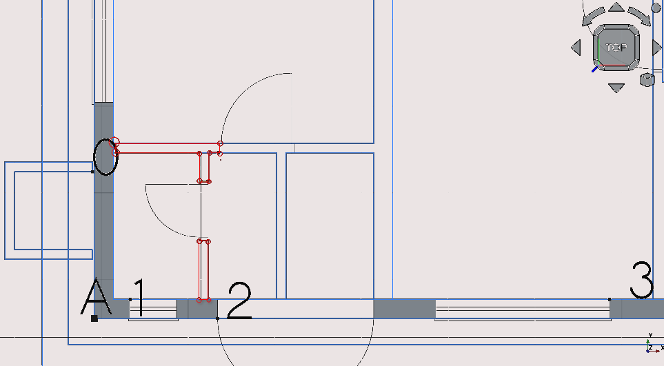
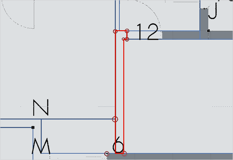
Use the polyline tool to trace the closed loops shown in red
Adjust each ‘show face’ property to true for each wire
Add the created wires to the group labelled ‘walls’
Creating the remaining internal walls (part 7)
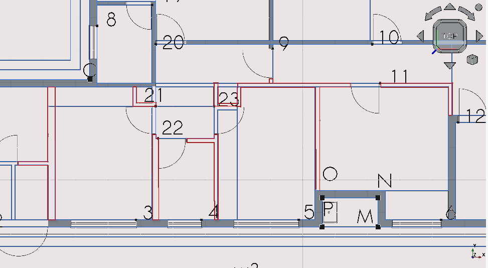
Repeat the previous steps to trace the closed loops in red shown above
Placing block v1
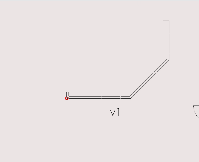
Select the object labelled v1 and use the move tool to place it at the point labelled c3
Step 7: creating ‘columns’
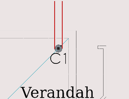
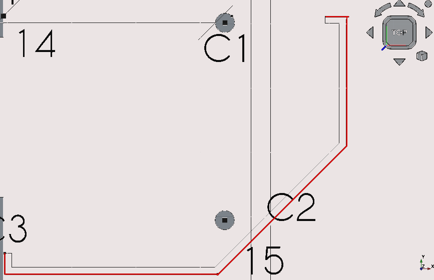
Creating a column at C1 (part 1)
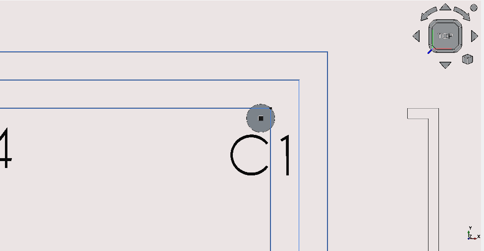
Press ‘C’ then ‘I’ or select the circle icon (
 )
)Select point C1
Navigate to Combo View>Tasks
Set the radius to 150 mm
Press 'Enter'/ select 'Ok'
Navigate to Combo View>Data
Set the face value property to false
Creating a column at C2 (part 2)
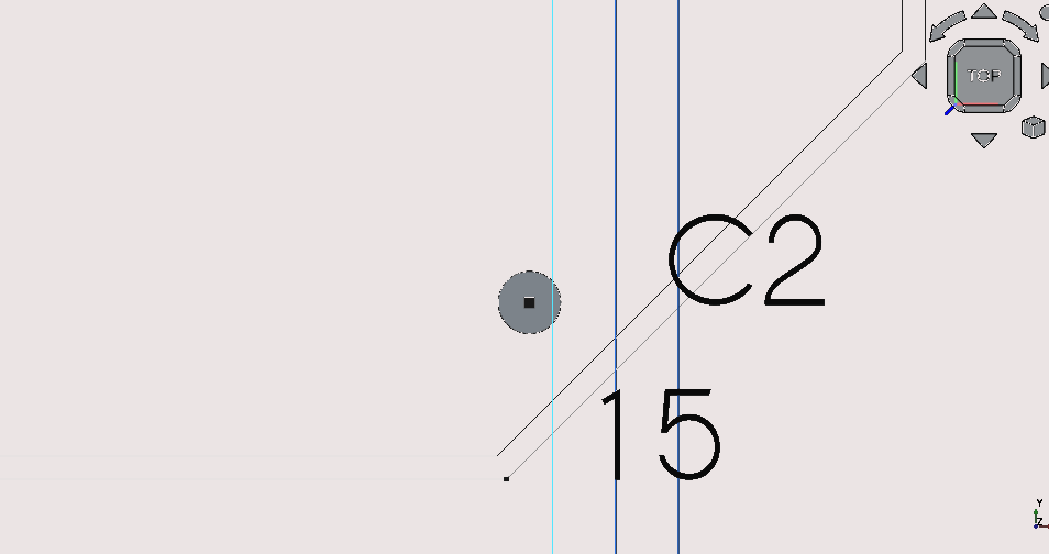
Press ‘C’ then ‘I’ or select the circle icon (
)Select point C2
Navigate to Combo View>Tasks
Set the radius to 150 mm
Press 'Enter' or select 'Ok'
Navigate to Combo View>Data
Set the face value property to false
Step 8: creating the ‘roof’
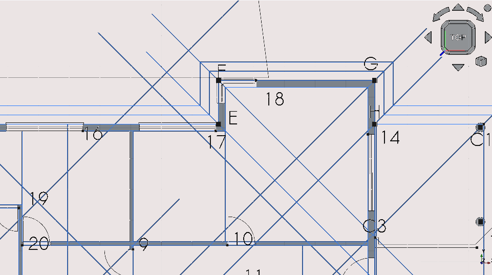
Creating a 45° line at point A (part 1)
Start construction mode by pressing ‘C’ then ‘M’ or by selection the construction mode icon (
)Press ‘L then ‘I’ or select the Line tool icon (
 )
)Select point A
Navigate to Combo View>Tasks
Select the angle check box
Set the angle to 45°
Select with the mouse arbitrarily far outside the building footprint
Creating a 45° line at point B (part 2)
Press ‘L then ‘I’ or select the Line tool icon (
)Select point B
Navigate to Combo View>Tasks
Select the angle check box
Set the angle to 45°
Select with the mouse arbitrarily far outside the building footprint
Creating a 45° line at point C (part 3)
Press ‘L then ‘I’ or select the Line tool icon (
)Select point C
Navigate to Combo View>Tasks
Select the angle check box
Set the angle to 45°
Select with the mouse arbitrarily far outside the building footprint
Creating a 45° line at point D (part 4)
Press ‘L then ‘I’ or select the Line tool icon (
)Select point C
Navigate to Combo View>Tasks
Select the angle check box
Set the angle to 45°
Select with the mouse arbitrarily far outside the building footprint
Creating a 45° line at point E (part 5)
Crop picture
Press ‘L then ‘I’ or select the Line tool icon (
)Select point E
Navigate to Combo View>Tasks
Select the angle check box
Set the angle to 45°
Select with the mouse arbitrarily far outside the building footprint
Creating a 45° line at point F (part 6)
Press ‘L then ‘I’ or select the Line tool icon (
)Select point F
Navigate to Combo View>Tasks
Select the angle check box
Set the angle to 45°
Select with the mouse arbitrarily far outside the building footprint
Creating a 45° line at point G (part 7)
Press ‘L then ‘I’ or select the Line tool icon (
)Select point G
Navigate to Combo View>Tasks
Select the angle check box
Set the angle to 45°
Select with the mouse arbitrarily far outside the building footprint
Creating a 45° line at point H (part 8)
Press 'L then 'I' or select the Line tool icon (
 )
)
Select point H
Navigate to Combo View>Tasks
Select the angle check box
Set the angle to 45°
Select with the mouse arbitrarily far outside the building footprint
Creating a 45° line at point C1 (part 9)
Press 'L then 'I' or select the Line tool icon (
)
Select point C1
Navigate to Combo View>Tasks
Select the angle check box
Set the angle to 45°
Select with the mouse arbitrarily far outside the building footprint
You may extend and trim lines using the trim tool (
 ):
(see using the trim tool: holding Ctrl will snap the trimmed
lines end to a Snap Point, pressing ‘alt’ inverts the trim
or extensions direction)
):
(see using the trim tool: holding Ctrl will snap the trimmed
lines end to a Snap Point, pressing ‘alt’ inverts the trim
or extensions direction)
Creating a 45° angle at point L (part 10)
Press ‘L’ then ‘I’ or select the Line tool icon (
)Select point L
Navigate to Combo View>Tasks
Select the angle check box
Set the angle to 45°
Select with the mouse arbitrarily far outside the building footprint
Creating a 45° angle at point L (part 11)
Use the trim tool to extend the 45° lines beyond the boundaries of the construction roofline See the section on 'using the trim tool' (holding Ctrl will snap the lines being trimmed to Snap Points; Pressing ‘Alt' inverts the trim or extensions direction). The procedure for extending a line is as follows;
Select the line that is to be extended
Press 'T' then 'R' or select the trim tool icon (
)
Select anywhere outside the boundaries of the building footprint
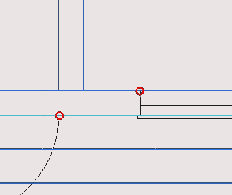
Drawing a horizontal line from an intersection point of 2 lines (part 12)
Ensure that the Intersection Snap toggle is on
Ensure that Construction Mode is toggled on (
)
and hover your mouse over the intersecting lines until the Snap
Intersection icon ( )
appears then select the vertex with the cursor
)
appears then select the vertex with the cursor
Press 'X' to constrain the line in the x-axis
Select outside the building footprint
Drawing a line from points c to d and moving it (part 13)
Press 'L' then 'I' or select the Line tool icon (
);hover
the mouse over c until the End Point Snap icon (
)
appears and select it do the same at c
Navigate to Combo View>Model/Construction
Select the last line object in the group
Select the line and press 'M' then 'V'
Press 'X'
Navigate to Combo View>Tasks
For Local ΔX enter in 3500 mm
Press 'Enter' or select enter point
Drawing a line from points (part 14)
Press ‘L then ‘I’ or select the Line tool icon (
)
Hover the mouse over the intersection circled in red and select the point (the Snap Intersection icon will (
)
appear when hovering over the intersection)
Making a line between points; C1 and L and offsetting it
(image must show c1 and L!)
Press ‘L then ‘I’ or select the Line tool icon (
)
Select point L
Press ‘Y’ and select C1 (using Snap Points)
Navigate to Combo View>Model>/Construction folder)
Select the newly created line
Press ‘O’ then ‘S’ then place the mouse cursor to the left side of the object
Navigate to Combo View>Tasks (don’t move the mouse as this decides in which direction the line will be offset)
Type -3500mm for the offset distance
Press 'Enter'
Creating a line between F and C3
Ensure that Snap Points are on, the most important of which would be Snap Intersection (
)
Press 'L' then 'I' or select the Line tool icon (
)
Select the two points highlighted red and displayed above
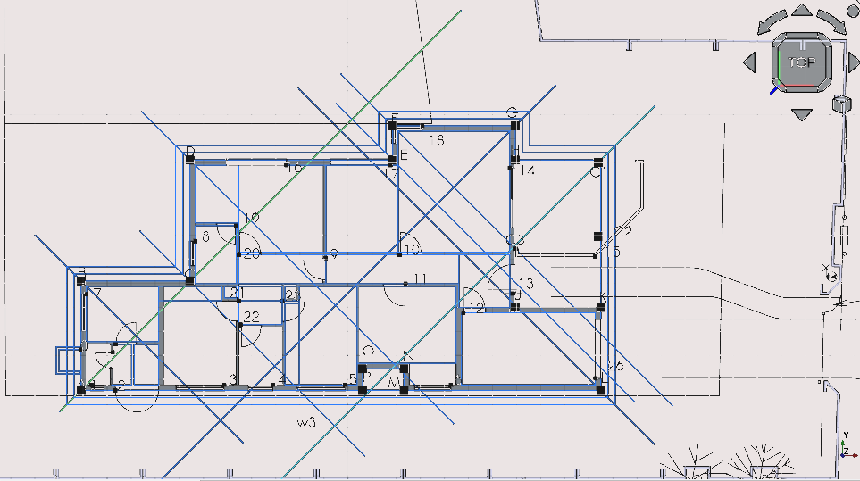
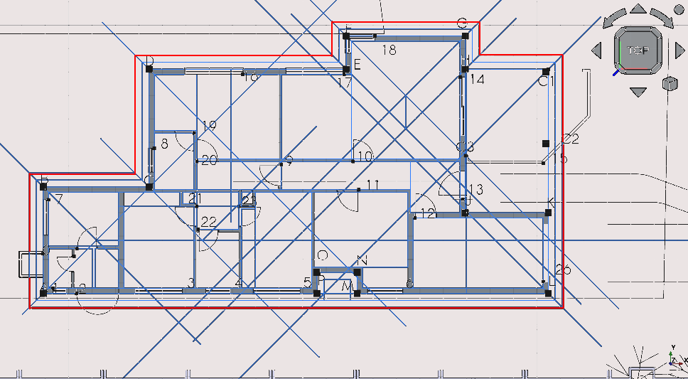
Step 9: tracing construction lines to create the ‘roof’
Creating a polyline for the ‘roof’ (part 1)
Press 'C' then 'M' or select the construction mode toggle icon (
 )
)
Press 'P' then 'Y' or select the Polyline icon (
)and
select the points to the left with Point Snap
Press 'Esc'
Option click the newly created polyline with the cursor
Select >Utilities>add to new named group
Type 'roof' in the pop-up menu (this creates a new named group called ‘roof’)
Press 'Enter'
Creating a polyline for the ‘roof’ (part 2)
Press 'P 'then 'Y' or select the Polyline icon (
)
and select the points shown in the image above
Press 'Esc'
Option click the polyline with the mouse and select >Utilities>add to group then select roof
Creating a polyline for the ‘roof’ (part 3)
Press ‘P’ then ‘Y’ and select the points shown in the image above
Press 'Esc'
Option click the polyline with the mouse and select >Utilities>add to group then select roof
Creating a polyline for the ‘roof’ (part 4)
Press ‘P’ then ‘Y’ or select the Polyline icon (
)
and select the points shown in the image above
Press 'Esc'
Option click the polyline with the mouse and select >Utilities>add to group then select roof
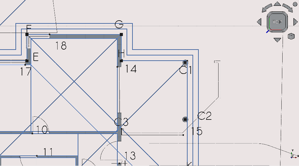
Creating a line between C3 and j (part 5)
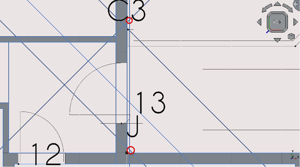
Press ‘P’ then ‘Y’ or select the Polyline icon (
)
and select the points shown in the image above
Press 'Esc'
Option click the polyline with the mouse and select >Utilities>add to group roof
Creating a polyline for the overall roof line (part 6)
Press ‘P’ then ‘Y’ or select the Polyline icon (
)Ensure Point Snap is on. Select all the points shown above
Press 'Esc'
Hiding construction lines (part 7)
Navigate to Combo View>Model
Select the group labelled ‘construction’
Press the Spacebar
Grouping the items representing the ‘roof’ (part 8)
Select any of the remaining polylines and lines shown above
Option click and select ‘move to named group’ and select the group labelled ‘roof’
Creating the ‘slab’ (part 9)
Press ‘P’ then ‘Y’ or select the Polyline icon (
)
and draw the shape shown above using what you have
learned so far
Step 10: placing furniture blocks
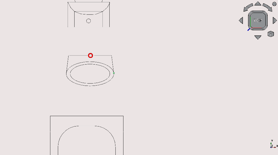
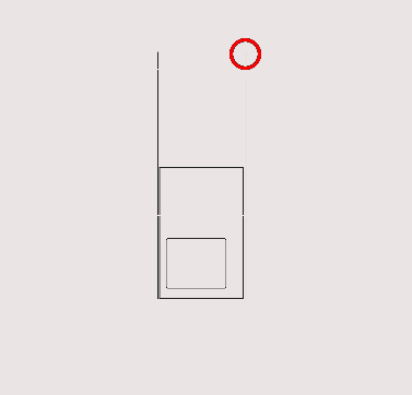
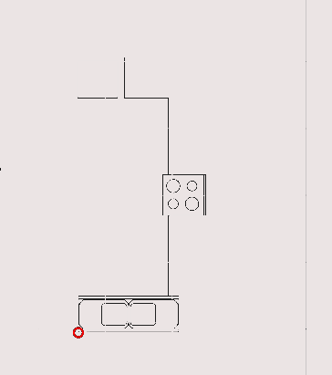
Placing the sink block (part 1)
Press ‘M’ then ‘V’ or select the Move tool icon (
)Select the block shown above
Select the point to move it from (The midpoint circled in red)
Select the copy option or press ‘P’ (Combo View>Task>Move): note this option stays on until toggled off when using the move tool
Pan such that the objects shown above are in view
Hover the mouse near the point shown above (the mid point of the wall) until the Snap Midpoint icon (
 )
appears
)
appearsThen select with your mouse
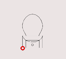
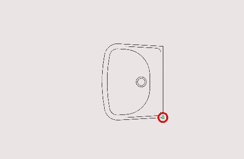
Placing the toilet block (part 2)
Press ‘M’ then ‘V’ or select the Move tool icon (
)Select the block shown above
Select the point to move it from (The midpoint circled in red)
Select the copy option or press ‘P’ (Combo View>Task>Move)
Pan so that the objects shown above are in view
Select the circled point shown above
Placing the kitchen cabinetry and sink block (part 3)
Press ‘M’ then ‘V’ or select the Move tool icon (
)Select the block shown above
Select the point to move it from (The midpoint circled in red)
Pan so that the objects shown above are in view
Select the circled point shown above
Placing the bathtub block (part 4)
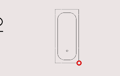
Press ‘M’ then ‘V’ or select the Move tool icon (
)Select the block shown above
Select the point to move it from (The midpoint circled in red)
Select the copy option or press ‘P’ (Combo View>Task>Move)

Pan so that the objects shown above are in view
Select the circled point shown above
Placing the sink block (part 5)
Press ‘M’ then ‘V’ or select the Move tool icon (
)Select the block shown above
Select the copy option or press ‘P’ (Combo View>Task>Move)
Select the point to move it from (The midpoint circled in red)
Press 'T' or select the continue check box under Combo View>Tasks>Move (this allows for objects to be moved multiple times without having to select the move tool multiple times)
Select the top right most point of the bathtub block (displayed above)
Combo View>Tasks
Toggle the continue check box under Combo View>Tasks>Move or press 'T'
Press 'Y'
For Local ΔY type in 145 mm
Press 'Enter' or select enter point
Placing the toilet (part 6)
Press ‘M’ then ‘V’ or select the Move tool icon (
)Select the block shown above
Select the point indicated above
Select the copy option or press ‘P’ (Combo View>Task>Move)
Press ‘T’ or select the continue check box under Combo View>Tasks>Move (this allows for objects to be moved multiple times without having to select the move tool multiple times)
Select the top right most point of the bathtub block (displayed above)
Combo View>Tasks
Uncheck the continue check box under Combo View>Tasks>Move or press ‘T’
Navigate to Combo View>Tasks>Move
For ‘Local ΔX’ type in 245 mm
For ‘Local ΔY’ type in 72 mm
Press 'Enter' or select enter point
Placing the kitchen counter block (part 7)
Press ‘M’ then ‘V’ or select the Move tool icon (
)Select the copy option or press ‘P’ (Combo View>Task>Move)
Select the block shown above
Select the point indicated above
Select the copy option or press ‘P’ (Combo View>Task>Move)
Select the point indicated above
Press ‘M’ then ‘V’ or select the Move tool icon (
)Select the copy option or press ‘P’ (Combo View>Task>Move)
Select the block shown above
Select the point indicated above
Press ‘T’ or select the continue check box under Combo View>Tasks
Pan so that the objects shown above are in view
Select the circled point shown above
Press ‘T’ or select the continue check box under Combo View>Tasks
Select the point shown above
Press ‘X’ and select the ‘walls’ edge
Moving the sink block (part 8)
Press ‘M’ then ‘V’ or select the Move tool icon (
)Select the copy option or press ‘P’ (Combo View>Task>Move)
Select the block shown above
Select the point indicated above
Press ‘T’ or select the continue check box under Combo View>Tasks
Moving the toillet block (part 9)
Press ‘M’ then ‘V’ or select the Move tool icon (
)Select the copy option or press ‘P’ (Combo View>Task>Move)
Select the block shown above
Select the point indicated above
Press ‘T’ or select the continue check box under Combo View>Tasks
Select the WC block and press ‘R’ then ‘O’
Navigate to Combo View>Tasks> rotate
For the ‘rotation angle’ enter 270°
Navigate to Combo View>Tasks> rotate
Enter 270°
Press 'Enter' 3 times
Placing and rotating the bathtub block (part 10)
Select the bathtub block
Press ‘R’ then ‘O’
Navigate to Combo View>Tasks>rotate
Select the copy option or press ‘P’ (Combo View>Task>Move)
Under rotation enter 270°
Press 'Enter'
Under rotation enter 270 again
Press 'T' or select the continue check box under Combo View>Tasks
Press 'P' or select the copy option (Combo View>Task>Move)
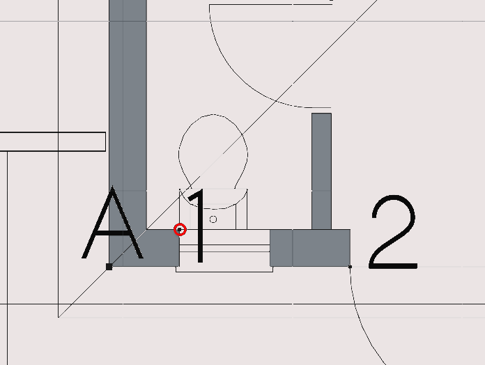
Select the point near point C shown in the image above
Press 'T' or select the continue check box under Combo View>Tasks
Press 'P' or select the copy option (Combo View>Task>Move)
Select the same point near point C
Navigate to Combo View>Task
For Local ΔX enter 20mm
For Local ΔY enter 20mm
Now that the blocks have been added to the floor plan select them and add them to a group
Create a group called 'windows' and add the window blocks
Create a group called 'doors' and add all the doorblocks
Create a group called 'utility' and add the bathtub, toilet, washbasin and cabinetry blocks to it. Hint: groups can be created by selecting the create group icon (
 )
or by option clicking on the file name in Combo View>Model
and selecting 'create group'. Items can be added to groups by
selecting them in Combo View>Model and option clicking and
selecting >move to group or by selecting the object itself in
the view
)
or by option clicking on the file name in Combo View>Model
and selecting 'create group'. Items can be added to groups by
selecting them in Combo View>Model and option clicking and
selecting >move to group or by selecting the object itself in
the view
Step 11: creating a cut
Creating a cut: Creating lines to serve as a reference (part 1)
Create two lines extending from the block
Make sure they cross over the ‘wall’ shown above
Creating a cut: Creating a rectangle (part 2)
Draw a rectangle where the lines and the ‘wall’ intersect
Hold Ctrl
Select the 'wall' first
Select the 'Rectangle'
Release Ctrl
Select the Downgrade icon (
 )
)
This subtracts Draft objects from each other
Remember to delete the lines you use as reference earlier or add them to the construction layer by selecting them and pressing the add to construction layer icon (
)
Tutorial 02 Part c: Annotations
Step 1: annotation and using the text tool
Using the text tool
Created text can be, like with other tools be used by:
Shortcut:pressing 'T' then 'E' or by selecting the Text icon (
 )
)
Press select button in any position on the drawing or by entering coordinates under Combo View>Tasks>Text
The text must then be typed in Combo View>Tasks>Text
Pressing enter or selecting create text under Combo View>Tasks>Text will complete the task
Label the floor plan created in the previous steps as shown in the image above
When done add all the dimensions of the floor plan into a group named ‘labels’
Creating the porch and ramp
Create rectangles representing:
Ramp (2800 by 2500mm)
Porch (1671 by 1500mm)
Then place them in the red highlighted positions shown in the image above
Step 2: annotation continued
Dimensioning the floor plan (part 1)
Make sure Point Snap is on (
)
Press 'D' then 'I' or selection the Dimension tool icon (
 )
)
Press 'T' (to continue and do more than 1 line of dimensions)
Select the first two points along the polyline highlighted in the image above; this sets the orientation of the dimension tool
Select the remaining points along the polyline For example: selecting two vertexes on a line will create a dimension parallel to said line
Select a suitable position for the dimensions relative to the floor plan
Press 'Esc'
You may also select a line before activating the dimension tool, this will create a dimension parallel to said line
Dimensioning the floor plan (part 2)
Press ‘D’ then ‘I’ or selection the Dimension tool icon (
 )
)Press ‘T’ (to continue and do more than one line of dimensions)
Select the first two points along the polyline highlighted in the image above
Select the remainder of the points along the line
Move the cursor away from the floor plan and select a suitable position for the dimension
Navigate to Combo View>Tasks>Dimension
Input the desired ‘Local ΔX’ and ‘Local ΔY’ values if wanted for dimension location
Press 'Esc'
Dimensioning the floor plan (part 3)
Press ‘D’ then ‘I’ or selection the Dimension tool icon (
)Press ‘T’ (to continue and do more than 1 line of dimensions)
Select the first two points along the polyline highlighted in the image above
Select the remainder of the points along the line
Move the cursor away from the floor plan and select dimension position
Navigate to Combo View>Tasks>Dimension
Input the desired ‘Local ΔX’ and ‘Local ΔY’ values for dimension location if desired
Press 'Esc'
Dimensioning the floor plan (part 4)
Press ‘D’ then ‘I’ or selection the Dimension tool icon (
)Turn Snap centre on (
 )
)Press ‘T’ (to continue and do more than one line of dimensions)
Select the first two points along the polyline highlighted in the image above
Select the remainder of the points along the line
Move the cursor away from the floor plan and select suitable dimension position
Navigate to Combo View>Tasks>Dimension
Input the desired ‘Local ΔX’ and ‘Local ΔY’ values if desired
Press 'Esc'
Hint: some objects require unique Snaps to interact with their geometry. In the case of circles you may want to use construction lines that run from the centre of the circle to their circumference and use the Snap Intersection (
 )
Snap when dimensioning
)
Snap when dimensioning
Dimensioning the floor plan (part 5)
Press 'D' then 'I' or selection the Dimension tool icon (
)
Turn Mid Point Snap on (
 )
)
Press 'T' (to continue and do more than one line of dimensions)
Select the first two points along the polyline highlighted in the image above
Select the remainder of the points along the line
Move the cursor away from the floor plan and select a suitable dimension position
Navigate to Combo View>Tasks>Dimension
Input the desired Local ΔX and Local ΔY values if desired
Press 'Esc'
Dimensioning the floor plan (part 6)
The lines that are to be dimensioned are all at different angles. To easily dimension these objects, one can select an edge instead and then select the dimension icon or enter the shortcut
Select the edge to be dimensioned
Press ‘D’ then ‘I’ or selection the Dimension tool icon (
)Press ‘T’ (to continue and do more than one line of dimensions)
Move the cursor away from the floor plan and select arbitrarily
Navigate to Combo View>Tasks>Dimension
Input the desired ‘Local ΔX’ and ‘Local ΔY’ values
Press ‘E’ or pick ‘select edge’
Select the next edge to be dimensioned
Move the cursor away from the floor plan and select arbitrarily
Navigate to Combo View>Tasks> dimension
Input the desired ‘Local ΔX’ and ‘Local ΔY’ values
Repeat the process until you have dimensioned the edges shown above
Press 'Esc'
Dimensions can also be modified with the move tool.
When done add all the dimensions of the floor plan into a group labelled ‘dimensions’
Tutorial 02 Part d: Style settings
Changing the style settings of text
Navigate to Combo View>Model
Option click on the group named ‘labels’ and select ‘add dependants to selections’
Navigate to Combo View>Tasks>Style settings
Select the Style settings icon (
 )
)Set the text style to Noto Sans and the text size to 250mm
Select ‘selected’
Select 'Ok' or press 'Enter'
Changing the style settings of dimensions
Navigate to Combo View>Model
Option select the group labelled ‘dimensions’ and select ‘add dependants to selections’
Select the Style settings icon (
)Set the text style to Noto Sans and the text size to 250 mm
Set the arrow style to Tick-2
Set extension lines to 10 mm
Select ‘selected’
Select 'Ok' or press 'Enter'
Changing the style settings of lines
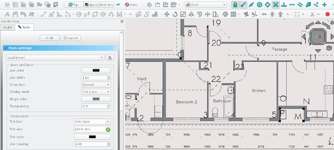
Navigate to Combo View>Model
Option select the group labelled ‘roof’ and select ‘add dependants to selections’
Select the Style settings icon (
)Set the draw style to dashed
Select ‘selected’
Select 'Ok' or press 'Enter'
Changing the style setting of wires
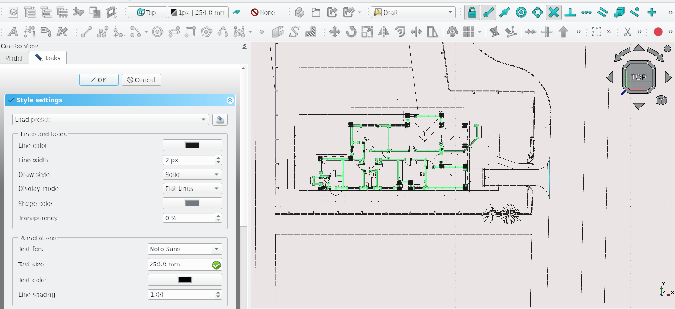
Navigate to Combo View>Model
Option select the group labelled ‘walls’ and select ‘add dependants to selections’
Select the Style settings icon (
)Set the draw style to dashed
Select ‘selected’
Select 'Ok' or press 'Enter'
Change the line width to 2 pixels
Tutorial 02 Part e: Hatching
How to hatch
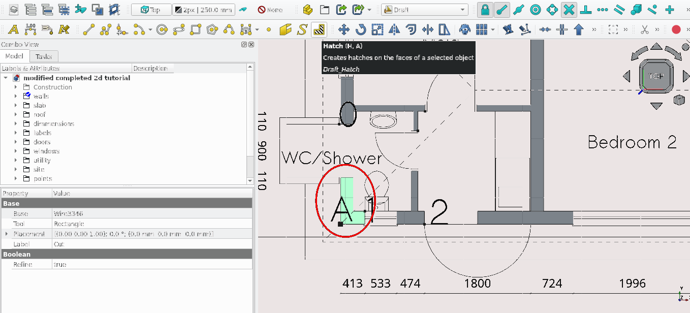
Select the wall shown above
Press 'H' then 'A' or select the hatch icon (
 )
)
Navigate to Combo View>Tasks>Hatch
Set the scale to 30
Leave rotation as 0
Select 'Ok' or press 'Enter'
Repeat these steps for the other wires in the 'walls' folder
Create a folder called 'hatches' and move all the hatches to it
Save the file (Ctrl+'S') navigate to file>save as (give it an appropriate name and save it in a location you can find later)
This concludes the tutorial
Freecad Architectural Work Tutorial