06
Creating 3D elements: Introduction to Building Information Modelling (BIM)
Terms of note
Working planes
A plane is an imaginary face one can create 2D geometry on in FreeCAD. There are multiple default planes such as:
The Top (XY) plane
The Front (XZ) plane
The Side (YZ) plane
You may also set a custom Working plane by selecting the face of any 3D object that is coplanar (flat)
vertex/vertices
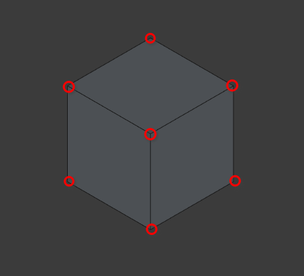
Like with 2D objects these are points where multiple edges meet. The only difference is that now the points have three axes where they can exist (3D)
Edge/edges
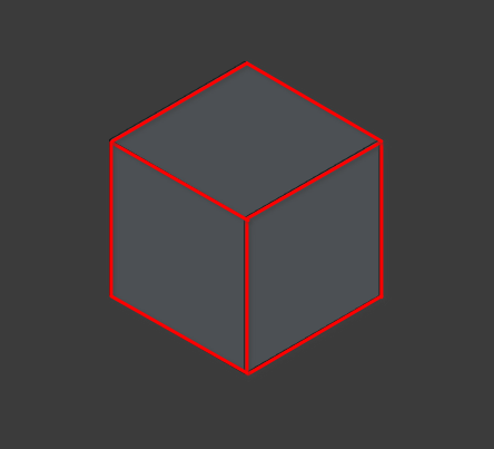
Like with 2D objects edges are lines that surround faces, the main difference being that edges have three axes where they can exist
Face/faces
A face is a plane that is created when surrounded by a closed loop of edges and vertices
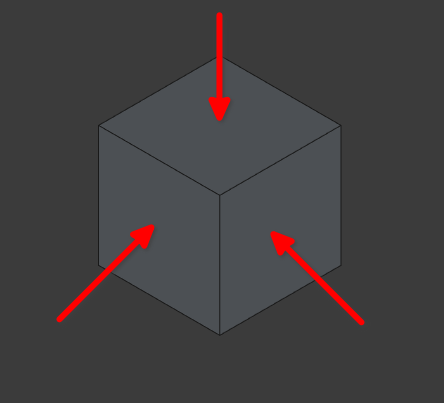
Normals
Normals are the direction 90° from a face in which a 2D face is extruded.
If the base 2D shape is used to create an Arch 3D object drawn in an anti-clockwise direction then the normal will be positive
If a 2D shape is drawn in a clockwise direction then the normal of the base shape will be in the opposite direction
Basic 3D And The Arch workbench
Part 1: Opening documents and preparing a file
Navigate to File>Open (select the drawing created in Tutorial 02)
Select the work bench icon and scroll to the Arch work bench icon (
 )
)
A key thing to note is that the easiest way to create 3D objects in FreeCAD is to base them off of 2D objects
Setting up Snap Points
Set the active working plane to top, by selecting the select plane icon (
 ), navigating to Combo View>Tasks and selecting Top (XY)
Select the Snap lock icon (
 ), this toggles Snaps on and off
Select the Snap End Point icon (
 ), this snaps objects to end points or vertices
Select the Snap Working Plane icon (
 ) this ensures objects are only drawn in the active plane
Turn on Snap Grid (
 ) this ensures that created objects can be snapped precisely to
the grid
) this ensures that created objects can be snapped precisely to
the grid
Ensure that the grid is active by toggling (select if not active) the grid icon (
 )
)
When working with 3D objects you will need to be able to view items at different angles, you can orbit by pressing the middle mouse icon and option clicking with the mouse while moving the cursor around (this only works if the cad navigation style is active)
Part 2: the Arch Wall tool
What is the Arch Wall tool?
The Arch
Wall tool is used to create 3D geometry representing walls. It
can be activated by pressing 'W' then 'A' on the keyboard or
selecting the Wall tool icon (![]() )
)
It is most effectively used when;
• Creating 2D
geometry
• Selecting the 2D geometry
• Pressing 'W'
then 'A' on the keyboard or selecting the Wall tool icon (![]() )
)
• The wall will then take the shape of the geometry and
will be parametric (its properties such as height, thickness etc
can still be modified)
• This can be useful for creating
walls with curved surfaces and/or complex shapes
Using the Combo View and Wall tool
• Press
'W' then 'A' on the keyboard or select the Wall tool icon (![]() )
)
• Navigate to Combo View>Tasks and look at the items
under Wall
1, We will first tell FreeCAD where to place the
wall:
• For Local ΔX enter 0.0mm
• For Local ΔY
enter 0.0mm
• For Local ΔZ enter 0.0mm
• Select
‘Enter point’ or press 'Enter'
2, We will then give the
wall Length, Height and Alignment properties
Press 'Y' on
the keyboard to limit the length of the wall to the y axis
•
Enter 3000 mm
• Enter the following under Wall options:
•
Length should read 3000 mm
• Width = 220 mm
•
Height = 3000 mm
• Alignment= centre
• Select
Enter point
• You may delete the wall if desired by
pressing 'Ctrl'+’Z’ to undo an action or by selecting the
item and pressing ‘Delete’ on the keyboard
Arbitrarily creating walls
• Press
'W' then 'A' on the keyboard or select the Wall tool icon (![]() )
)
• Select anywhere on the drawing (this is the starting
point of the wall)
• Select anywhere on the drawing (this
is the ending point of the wall)
• Select the created
wall
• Combo View>Model>Data
• Press 'Ctrl'
then Z on the keyboard
• Select the newly created wall and
press ‘Delete’ to delete the wall if desired
Using snap points and the Arch Wall tool
Press 'W' then 'A' on the keyboard or select the Wall tool icon (
 )
)Ensure Grid Snap is toggled on (
)Ensure Snap Endpoint is toggled on (
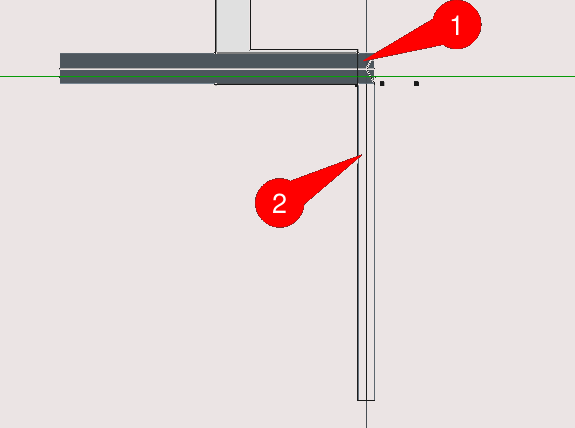
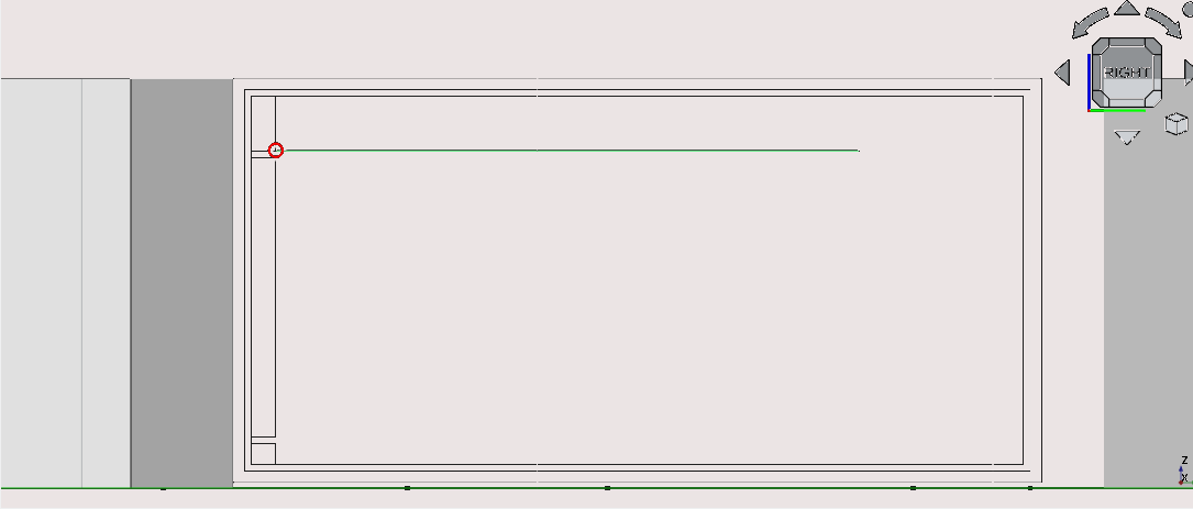
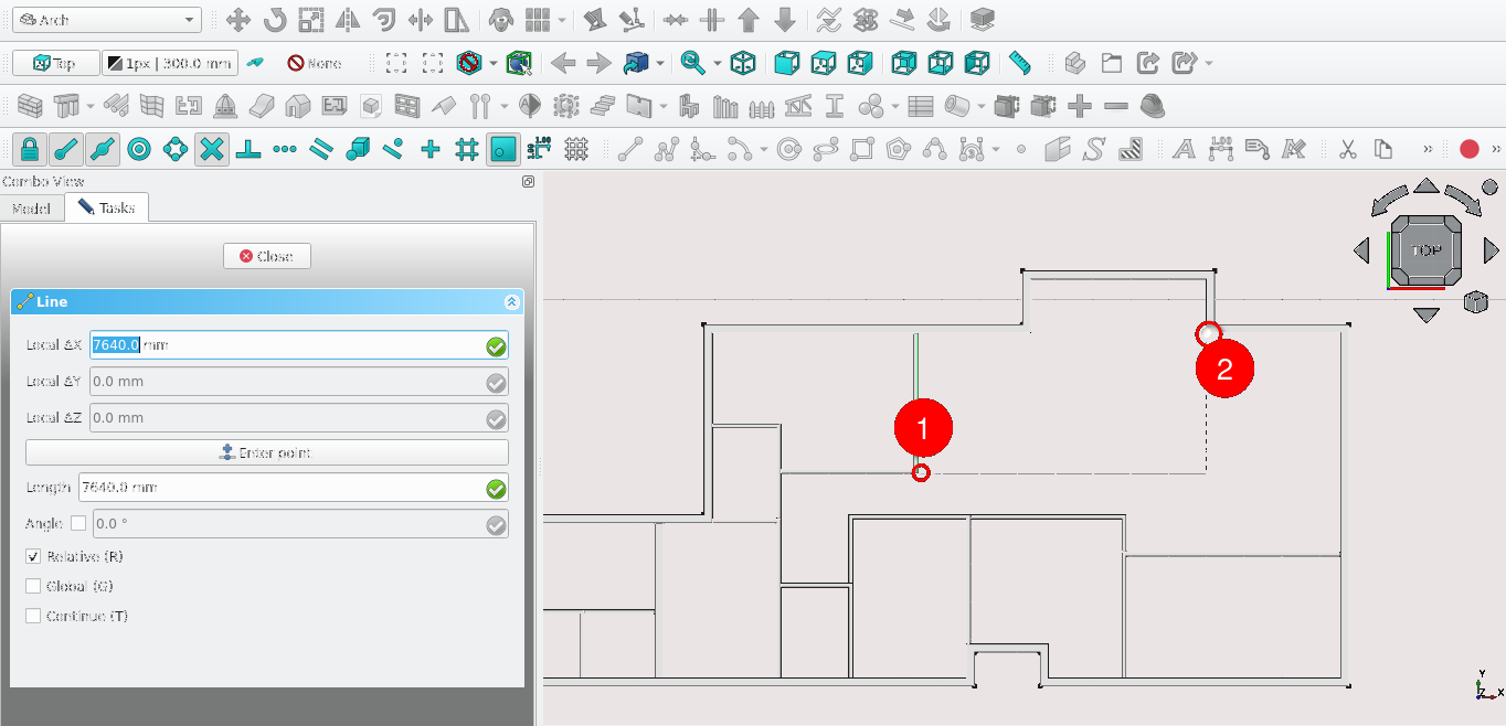
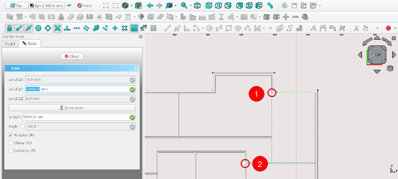
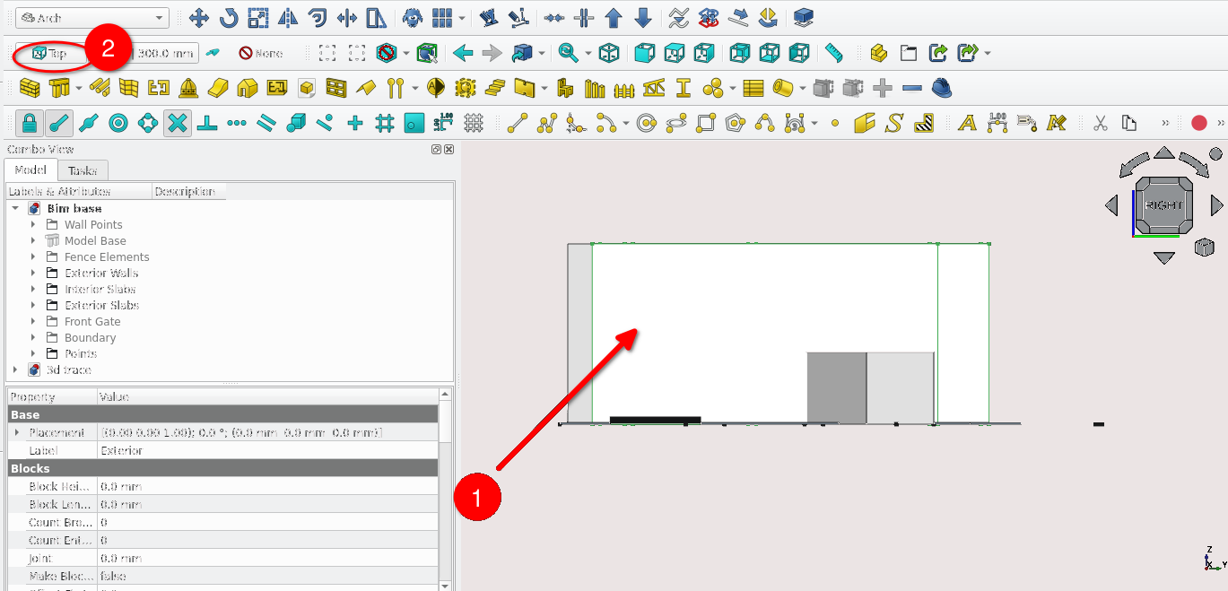
)Select the point indicated above (hover the mouse over the point until the grid snap icon appears before selecting it with the mouse)
Select the point indicated in the image above
Set the: Width to 220 mm, set the Height to 3000 mm and set the alignment to Centre
Select a point 1 grid unit below the point previously selected (this will end the task)
If you select the newly created wall and navigate to Combo View>Data you will notice that under Component then Base there is a Line object this is because most Arch 3D objects are based on 2D objects
You may also see the sub-components of a line by selecting the small triangular arrow next the object in Combo View>Model.
Do not delete this object as it will be used in task 2
Task 1
• Create
a wall at the origin of length 3000 mm, width 220 mm and height
3000 mm (make sure it is parallel with the y axis)
•
Create a wall using existing 2D geometry as a base
Steps for task 1
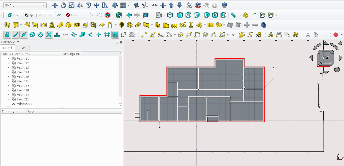
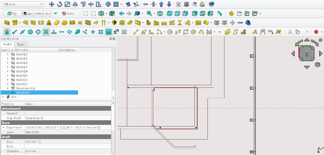
• Select
the wire shown above
• Press 'W' then 'A' on the keyboard
or select the Wall tool icon (![]() ). This uses the existing 2D shape as a base for the wall (both
sketches and items created in the Draft workbench can be used as
bases to create walls)
). This uses the existing 2D shape as a base for the wall (both
sketches and items created in the Draft workbench can be used as
bases to create walls)
• Navigate to Combo View>Data
(with the wall selected)
• Change the Align property to
Centre and the Height property to 3000 mm
Part 3: the Arch Add/Remove tool
What is the Arch Add/Remove tool?
• The Add
component tool (![]() ) combines two objects together to form one object
) combines two objects together to form one object
• It is
somewhat similar to the upgrade and downgrade tool however
objects still retain their parametric properties
• The
second object selected will become a component of the first
object
The Remove component tool (![]() ) subtracts one object from another creating a gap where the two
objects intersect
) subtracts one object from another creating a gap where the two
objects intersect
• The second object selected will become
a component of the first object
• Note: both tools do not
have a keyboard shortcut and should be selected after:
1,
Selecting the object you wish to use for adding or removing
volume
2, Selecting the object you wish to add or remove
volume to
Simply/ rephrase
Task 2
Combine the two walls created in the section called "Using snap points and the Arch Wall tool" and the section called "Task 1"
Steps for task 2
•While
holding 'Ctrl' key on the keyboard:
1, Select the wall
created in the section called "Using snap points and the
Arch Wall tool"
2, Select the created wall in the
section called "Task 1"
3, Release the 'Ctrl'
key
4, Select the Arch Add icon (![]() ) found in the tool bar
) found in the tool bar
• Note that because the two faces
of the walls are flush with each other their volume will join to
form one wall
Part 4: the Arch Structure tool
What is the Arch Structure tool?
• The Structure tool is generally used to make columns, slabs
and beams
• By default selecting the Structure tool icon
(![]() ) gives access to presets displayed under Combo
View>Tasks>Structure options
) gives access to presets displayed under Combo
View>Tasks>Structure options
• It can however, like the wall tool, be used in conjunction with sketches or Draft objects, though the 2D geometry used must have a face to extrude
Task 3
Create a slab within the bounds of the newly combined walls. Use a rectangle as a base and give the slab a height of 100 mm
Steps for task 3
1, Ensure
that the active plane is set to top (![]() )
)
2, Ensure that Snap Lock is toggled on by selecting the
icon (![]() )
)
3, Ensure that Working plane snap is on (![]() )
)
4, Ensure that Endpoint snap is on (![]() )
)
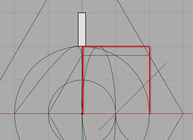
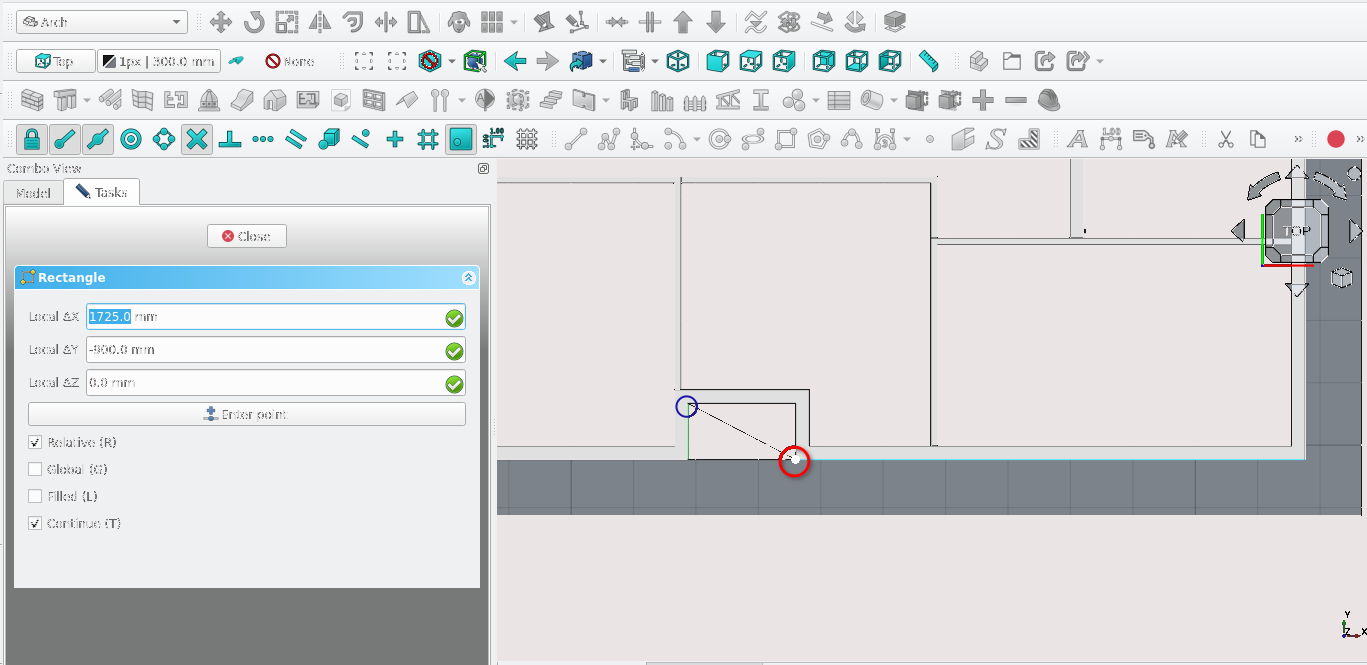
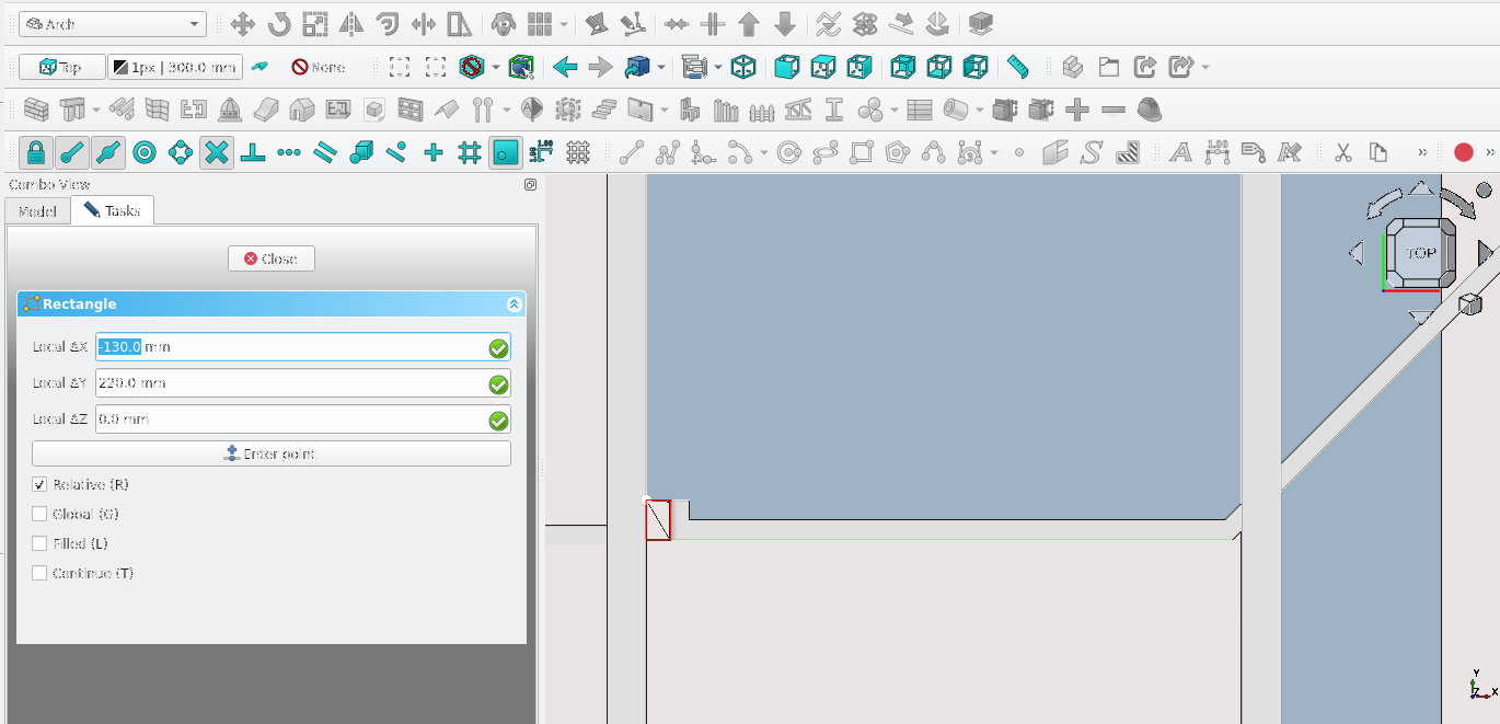
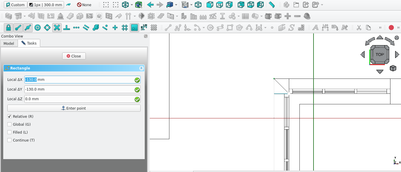
5, Press 'R' then 'E' on the keyboard or select the
Rectangle tool icon (![]() )
)
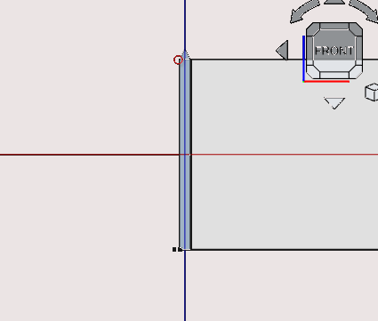
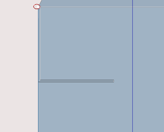
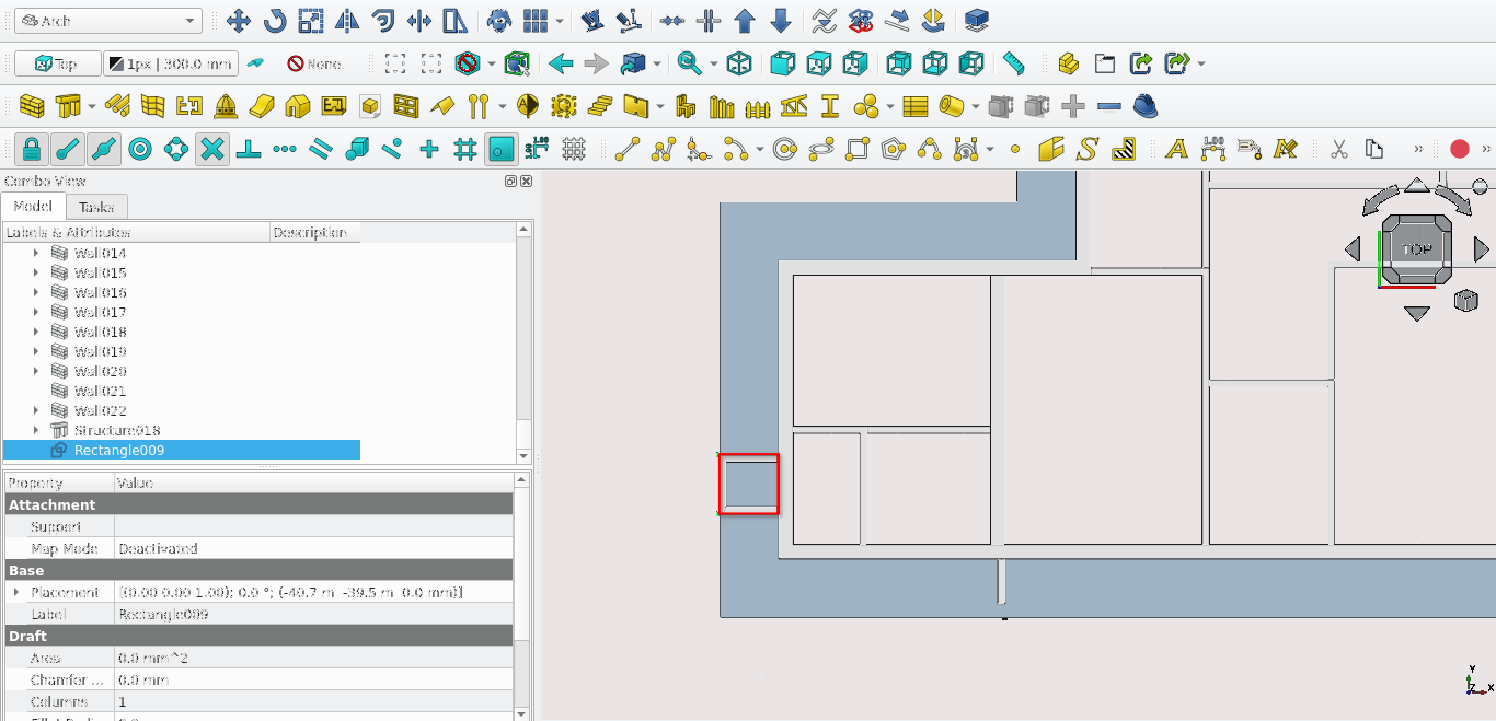
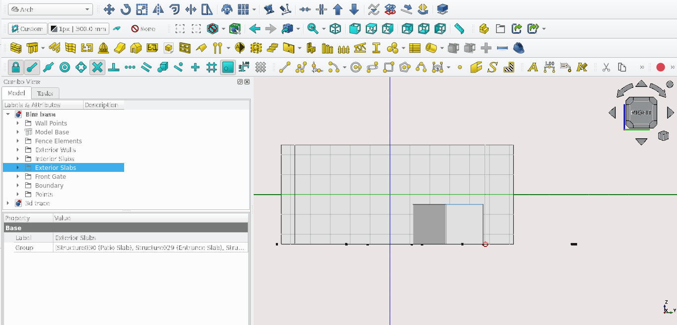
6, Select the two points indicated in the image below
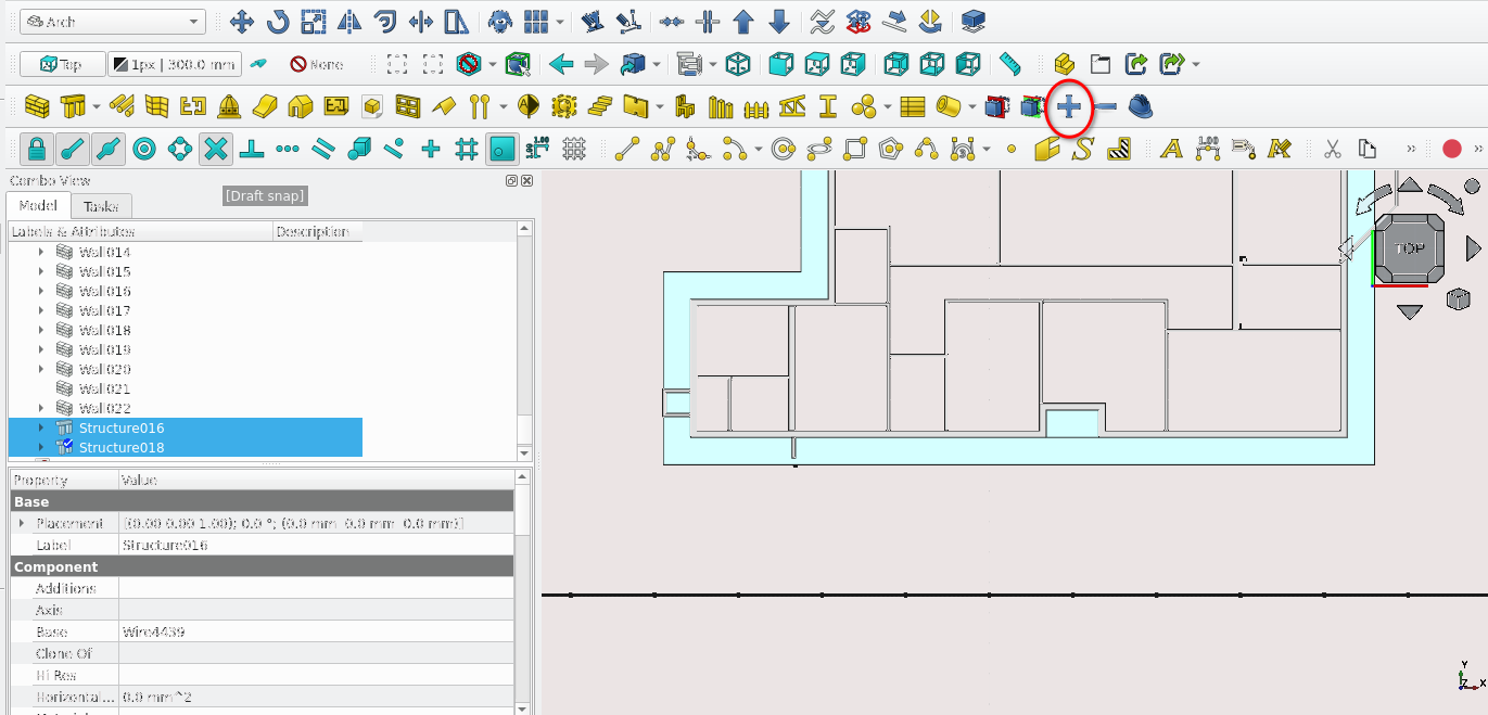
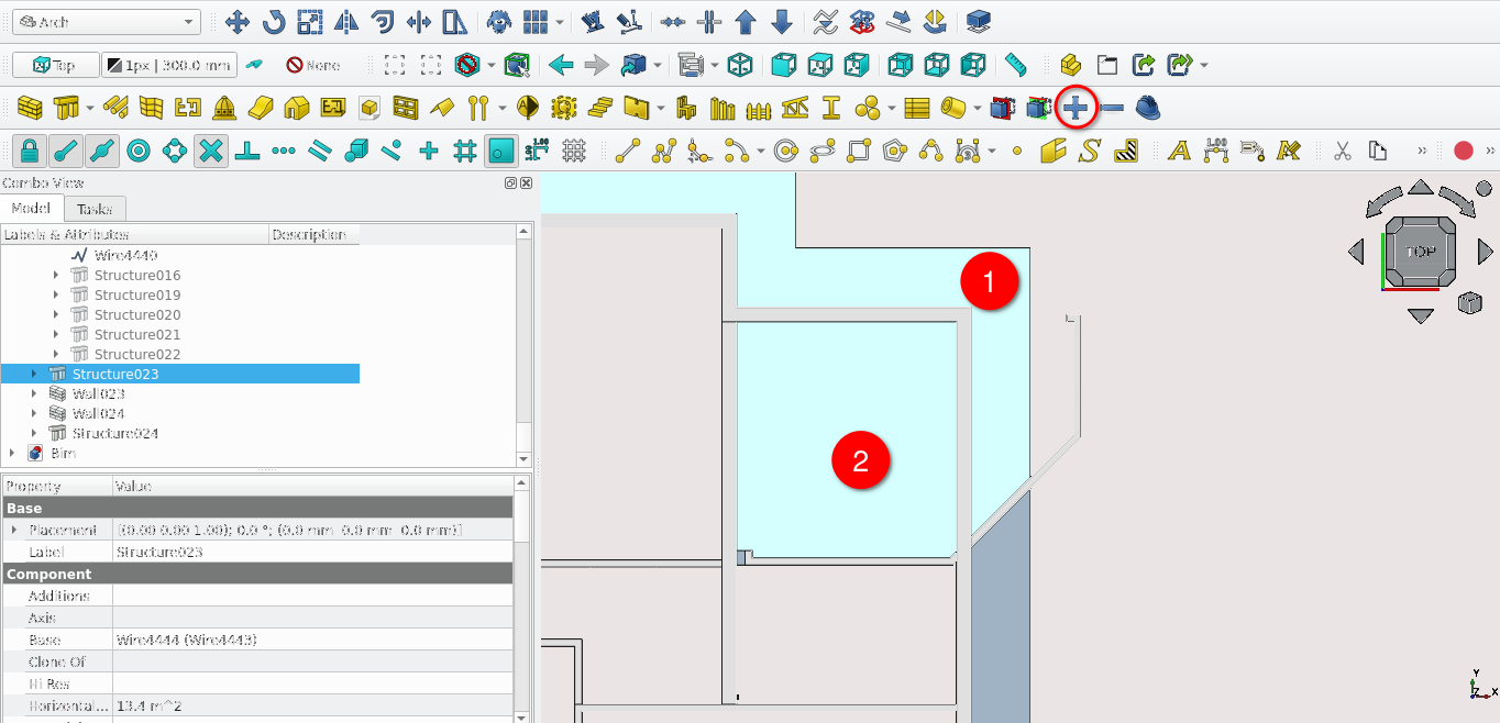
7,
Select the newly created rectangle
8, Select the structure
icon (![]() )
)
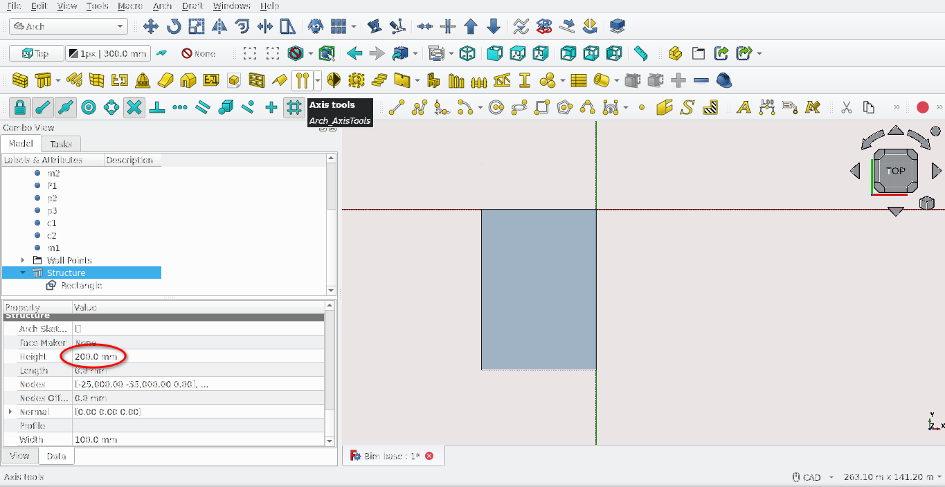
9, Select the newly created structure and navigate to
Combo View>Data>Structure then set the Height property to
100 mm
Part 5: the Arch Roof tool
What is the Arch Roof tool?
• A tool that creates roof geometry using a 2D base
• The Roof tool can be activated by either selecting the Roof tool icon (
 ) or pressing 'R' then 'F' on the keyboard
• A base 2D shape must be selected before starting the Roof tool
• As mentioned before, the direction of the base 2D shape determines the normal (direction for which the shape is extruded)
• This also applies to the Roof tool as drawing a polyline base for the Roof tool in a clockwise direction inverts the the normal of the shape and thus also that of the pitch of the roof, essentially making the roof upside down
Task 4
Create a roof on top of the combined walls created in task 2
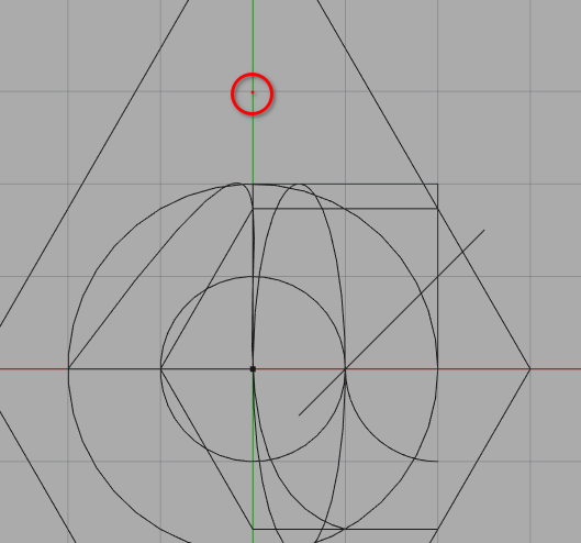
Task 4 Steps
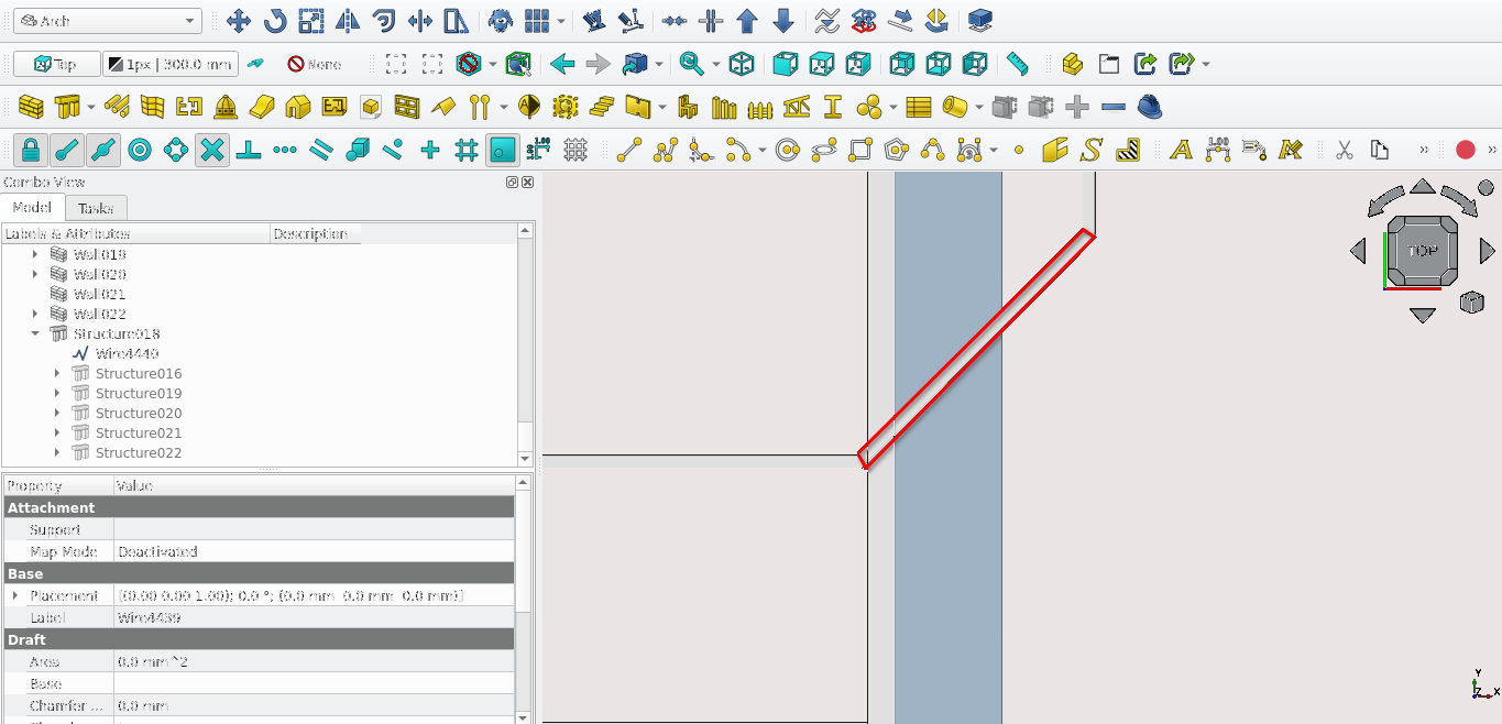
Fix picture in text file
• Select the top of the wall as the active plane (select the
walls top face and then select the active plane icon (![]() )
)
• Press 'P' then 'Y' on the keyboard or select the
Polyline tool icon (![]() ) and draw the shape in red shown in the image above
) and draw the shape in red shown in the image above
•
Select the newly created wire
• Press 'R' then 'F' on the
keyboard or select the Arch Roof tool icon (![]() )
)
• To edit the properties of the
created roof:
1, Double-select the item in Combo
View>Model
2, Navigate to Combo View>Tasks
Under
the item labelled roof the following properties will be
displayed;
a, Id: The number value corresponding to a roof
plane
b, Angle (pitch of the roof or roof angle)
c, Run: how
long the plane extends from the ridge
d, Overhang: how much
the roof is offset from its starting polyline
e, Height:
Distance from the lowest point of the roof to its ridge (excludes
thickness)
f, Idrel: the roof plane referenced for
automatic calculations
• Each line corresponds to a roof
plane starting at 0 and going anti clockwise (the first segment
of the polyline created will correspond with the roof plane 0)
•
Tip: Idrel is the plane you wish the current plane to stop at. By
default its value is -1, you can set the angle and run to 0 and
the idrel value to another roof plane number for more automatic
calculations
3, Set all roof slope angles to 15°
4,
Set all runs to 1200 mm
5, By default the overhang property
for each plane will be 100 mm: leave this value as is
6,
Select close in Combo View>Tasks or press 'Esc' on the
keyboard to end the task
The Arch Window tool
What is the Arch Window tool?
•The
window tool is somewhat of a misnomer as it is used to create
both windows and doors
• The window tool can be activated
by by pressing 'W' then 'N' on the keyboard or by selecting the
Window tool icon (![]() )
)
• The tool can be used in two ways:
a, By
selecting a pre-existing Sketch or Draft object and selecting the
Window tool icon or using the shortcut (see above)
b, By
activating the window tool and selecting from a list of presets
in Combo View>Tasks and selecting a desired location
•
Windows and doors can be placed within hosts. These can be Arch
objects such as walls or structures
Task 5
Create a single pane window on the right side of the building and create a custom door on the left side of the wall
Task 5 steps
1, Press 6
on the keyboard
2, Select the left-most wall then select the
Draft Select Plane icon (![]() )
)
• Ensure that Snap Working Plane is toggled on (![]() )
)
• Ensure that Grid Snap is toggled on (![]() )
)
3, Press ‘W’ then ‘N’ on the keyboard or select
the window tool icon (![]() )
)
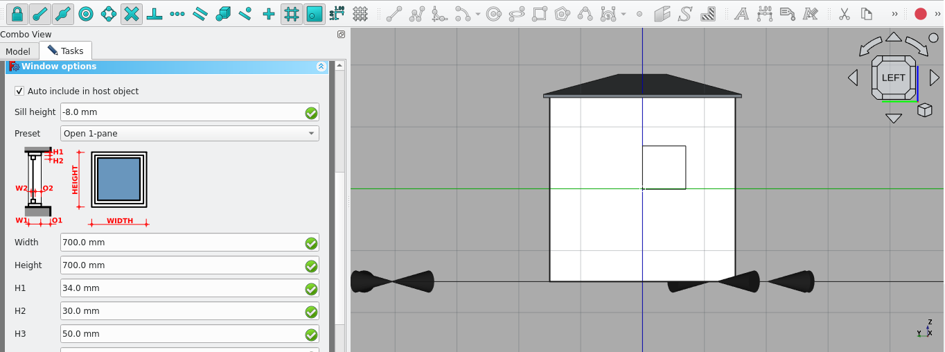
4, Navigate to Combo View>Tasks and scroll down to
Window options
• Presets and their options are shown
here
5,Select Open 1-pane from the Preset list
6,
Select the origin point on the wall (where the green and blue
line intersect as shown below)
7, Press
'3' on the keyboard
8, Select the wall then select the Draft
Select Plane icon (![]() )
)
• Ensure that Snap Working Plane is toggled on (![]() )
)
• Ensure that Grid Snap is toggled on (![]() )
)
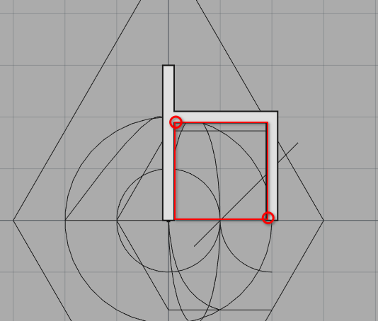
9, Select the point shown above: hover the mouse over the
point until the Grid Snap icon appears (![]() ) then select the point (the icon appearing indicates that the
placed object will be snapped precisely)
) then select the point (the icon appearing indicates that the
placed object will be snapped precisely)
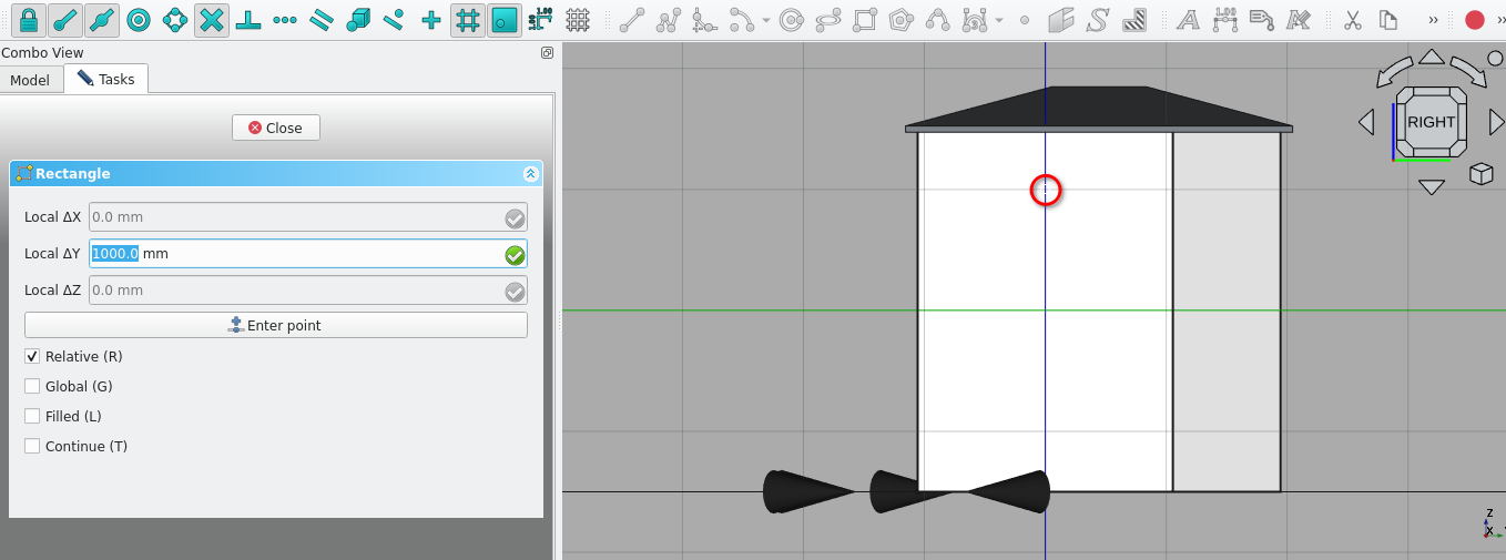
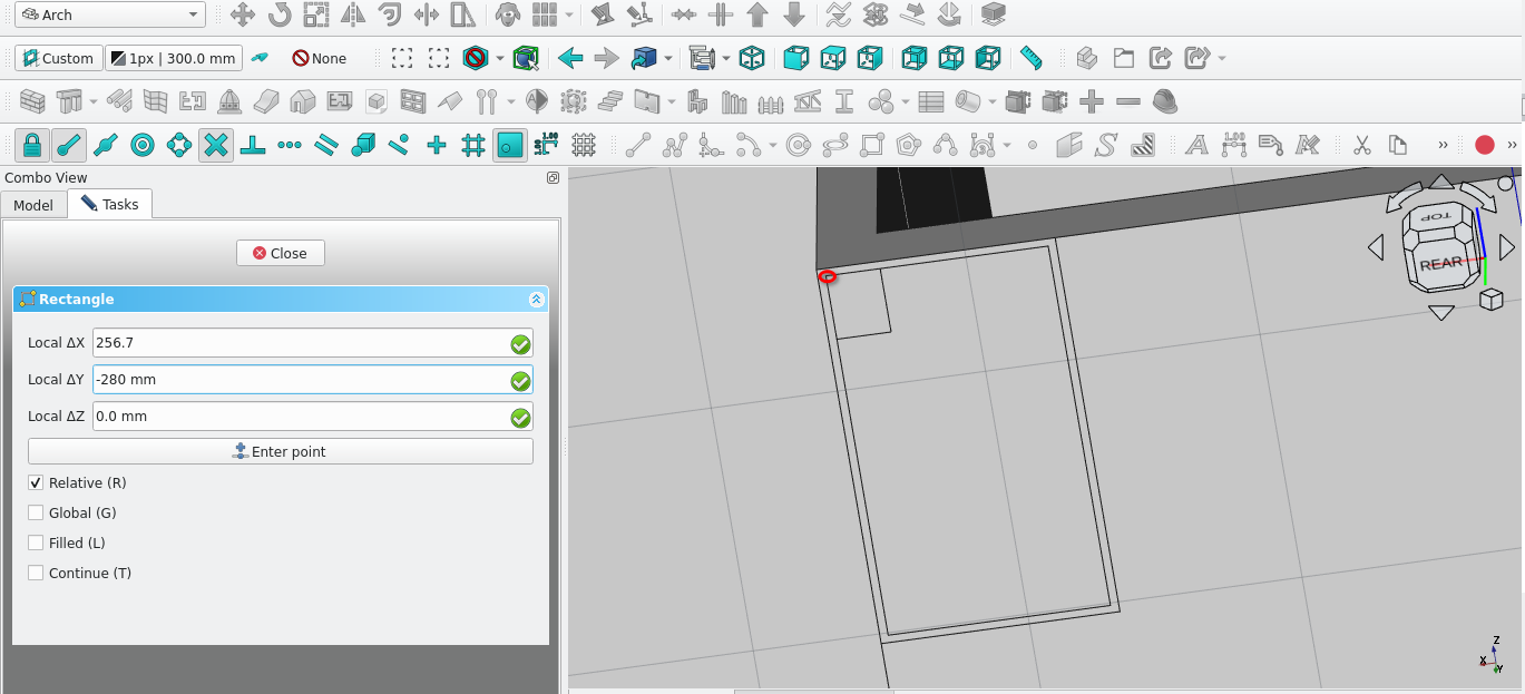
10, Navigate to
Combo View>Tasks>Rectangle
11, For Local ΔX enter 830
mm
12, For Local ΔY enter -2200 mm
13, Select ok under
Combo View>Tasks or press 'Enter' on the keyboard
14,
Select the newly created rectangle
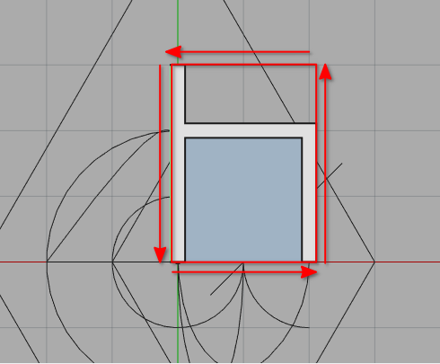
15, Press ‘O’ then
‘S’ on the keyboard or select the Offset tool icon (![]() )
)
16, Move the cursor of the mouse inside the rectangle
17,
Type in 35 mm (Combo View>Tasks>Offset)
18, Press
'Enter' on the keyboard
19, Select the two newly created
rectangles in Combo View>Model (hold 'Ctrl' and select one
after the other)
20, Release the 'Ctrl' key
21, Select
the Draft2sketch icon (![]() )
)
22, Select the newly created sketch and press 'W' then 'N'
on the keyboard or select the Window icon (![]() )
)
Fix picture in text
23,
Navigate to Combo View>Model and double-select the newly
created window
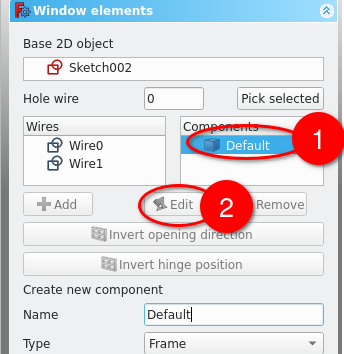
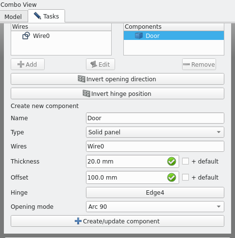
24, Navigate to Combo View>Tasks under
components, then select the item labelled Default and then select
the displayed Edit icon
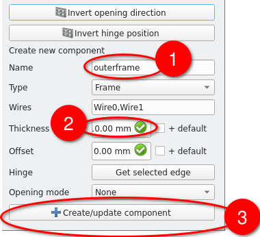
25, Under
the name field enter outerframe
• By default the Type
field will be frame, leave it as is
26, Set the thickness
field to 110 mm
27, Leave the offset field as 0 mm
28,
Select Create/update component
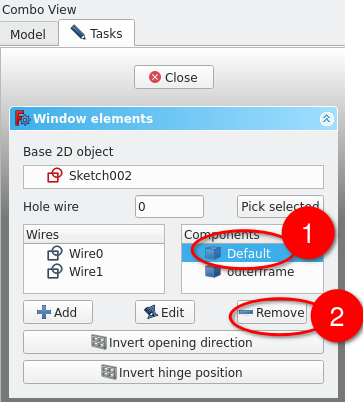
29, Select
the component labelled Default
30, Select remove
31, Select
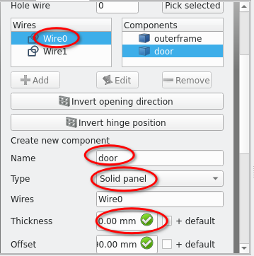
Add then in the name field type in 'door'
32, Set the Type
field to Solid panel
33, Type 20 mm in the the thickness
field
34, Type 90 mm in the Offset field
35, Select
Create/update component
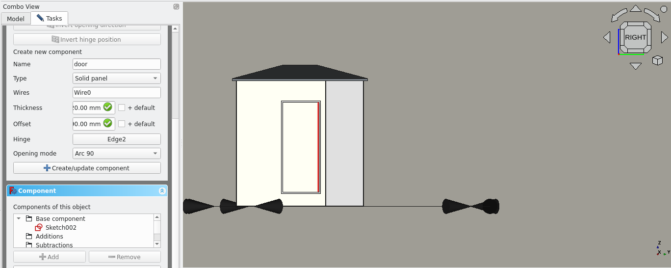
36,Select the Component labelled door and select edit
37,
Select the edge shown in the image above
• Ensure that you
are selecting the sketch of the door edge, not the door
itself
38, Navigate to Combo View>Tasks>Window
elements and select the Hinge field
39, Set the opening mode
to Arc 90
40, Select Create/update component
41, Press
'Esc' on the keyboard or select close under Combo View>Tasks
42,
Select the newly created window and navigate to Combo View>Data
43, Under Window select the Hosts field (…) icon and select the wall created in task 2
Creating A Bim Model Tutorial V
Introduction
In this Tutorial you will Learn how to a create 3D model of a house. It is highly recommended that you complete the previous tutorial on basic Arch objects
Bim
BIM or building information modelling is a means to represent a building or other assets in a 3D space. The 3D objects may contain additional information such as dimensions, materials, areas, levels, finishes and cost
Part 1: opening a file
For Windows: File>open /programfiles/FreeCAD/BIMTutorial.FCStd
For Linux:File> open home/.local/share/FreeCAD/BIMTutorial.FCStd
Part 2: creating The model base
Snap and view set up
Press 2 on the keyboard; this changes the view to the top view of the model
Select the set Active working plane icon (
) and choose Top (X,Y)
Under Combo View>Tasks toggle Snap lock (
) and ensure the following are toggled on:
• Snap Endpoint(
)
• Snap Midpoint( )
)
• Snap Working Plane (
)
Snap Grid (
)
Press 'R' then 'E' on the keyboard or select the Rectangle tool icon (
 )
)
Select the Origin with Snap Grid then enter these details:
For Local ΔX enter -50 m
For Local ΔY enter -60 then select Enter Point or press 'Enter'
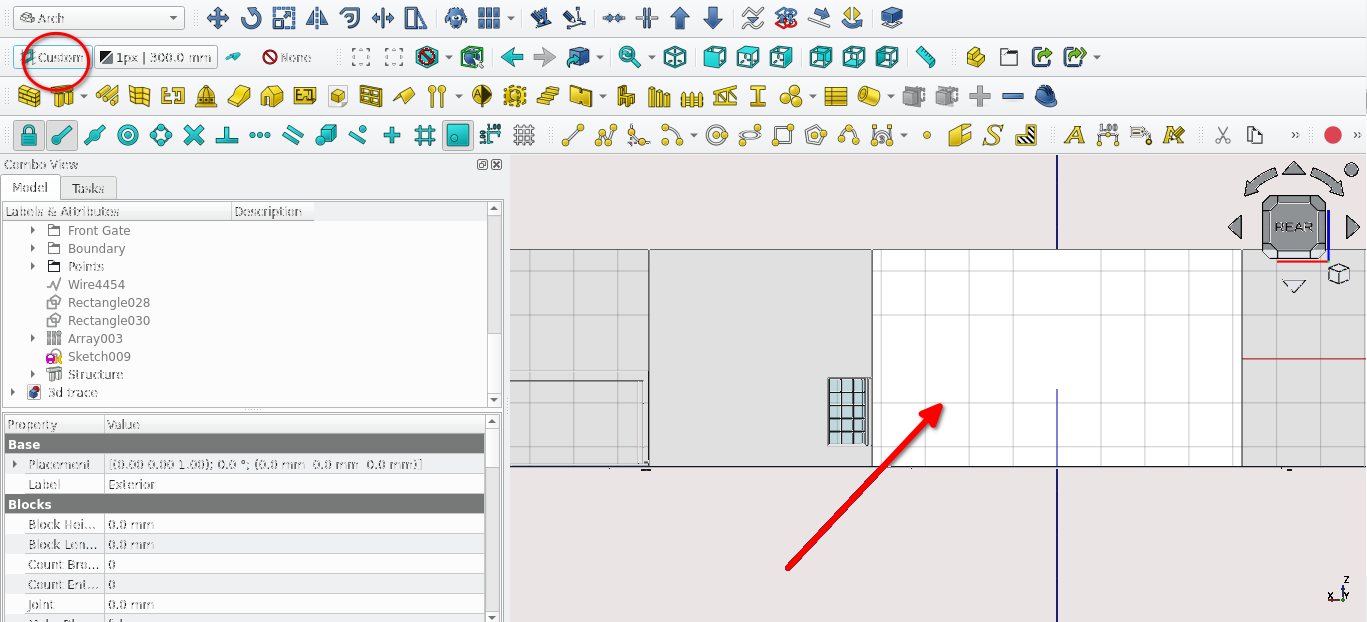
Creating a structure base from a rectangle
Navigate to Combo View>Model Select the newly created rectangle then select the Structure tool(
 )
)
Navigate to Combo View>Model select the item labelled ‘Structure’
Under Combo View>Data enter 200 mm for the height property
Press ‘M’ then ‘V’ on the keyboard or (
 ) Select the point at the origin
Toggle off the Snap point and Snap Working plane
For Local ΔZ Enter -200 mm
Navigate to Combo View>Model and select the item labelled structure and press ‘F2’ to rename it as Model Base
Part 3: Creating a boundary wall
Snap and view set up
Turn on Snap lock (Select the Snap lock icon (
) and the following:
• Snap Endpoint(
)
• Snap Midpoint(
)
• Snap Working Plane(
)Press 2 on the keyboard
Pan and zoom to the point labelled 1 (the points are labelled in the Combo View>Model list)
Press ‘V’ then ‘3’ on the keyboard to change the Draw Style to Wireframe or Navigate to main toolbar View>Draw Style>Wireframe
Creating a polyline or wire
Press 'P' then 'Y' on the keyboard or select the Polyline tool icon (
 )
)
Select the point labelled 1
Press 'Y', enter 450 mm
Press 'X' and enter 2735 mm
Press 'Y' and enter -450 mm
Select the newly created wire
Making a wall from a wire for the boundary wall
Press 'W' then 'A' on the keyboard or select the Wall tool icon (
)
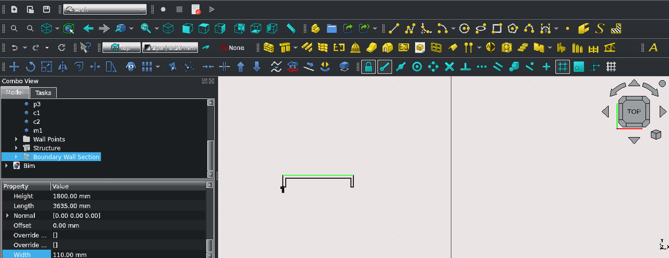
Navigate to Combo View>Model and select the newly created wall
Navigate to Combo View>Data and scroll down then change the following properties; Align: Left, Width: 110 mm, Height: 1800 mm
Press ‘F2’ and label the item as ‘Boundary Wall Section’ and press ‘Enter’
The Draft Array tool in brief
What is the draft array tool?
The array tool creates multiple copies of a selected object
It uses global axes when making copies or arrays of objects meaning that created arrays are independent of the active plane (X and Y will always be in the top plane)
The tool does not have a keyboard shortcut but is activated by selecting the Array tool icon (
 )
)
Using the array tool to make multiple copies of a wall
Navigate to Combo View>Model and select the item labelled ‘Boundary Wall Section’
Select the Array tool icon (
)
Input the following data:
For the Number of elements: input 14 for the x value and leave the y and z values as 1
For the X intervals: input 2750 mm for the x value, for the y value input 0 mm, for the z value input 0 mm. For the Y and Z Intervals: input 0 mm for all fieldsSelect the link array check box
Select 'Ok' to complete the process
Navigate to Combo View>Model and select the newly created array
Press ‘F2’ and relabel it to ‘Boundary Wall’
The Arch cut with Plane tool in brief
The Arch Cut with plane tool uses the face of an existing object to created a projection to cut another 3D object
It can be used by first selecting the object to be cut
Holding 'Ctrl'
Selecting the face to be used as a cutting plane, selecting the Cut with plane tool icon (
 )
)
Navigating to Combo View>Tasks and under Cut Plane selecting the appropriate side to cut (a preview is shown during the task)
Select 'Ok' to finish the task
Part 4: Creating a fence
Snap and view set up
Navigate to the point labelled 1
Turn on Snap lock (
) and the following ; Snap Endpoint (
), Snap Midpoint (
), Snap Working Plane (
), Snap Grid (
)
Creating a post for the fence
Press ‘R’ the ‘E’ on the keyboard or select the Rectangle tool icon (
)
Select the point labelled 1 as the starting point for the Rectangle
Navigate to Combo View>Tasks. For Local ΔX enter -100 mm, for Local ΔY enter -55 mm
Press ‘Enter’ on the keyboard or Select Enter point
With the newly created rectangle selected, select the Structure tool icon (
)
With the newly created structure selected, navigate to Combo View>Data
Under structure set the Height property to 1900 mm
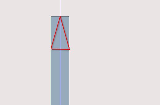
Press 6 on the keyboard to change the view to the left view
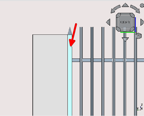
Select the face of the structure displayed then select the active plane icon) use the polyline tool and create the same wire shape shown below (the triangle should have a height of 100 mm)
Hint: use construction lines to create the base of the rectangle so you have something to snap to when using the polyline tool
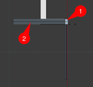
Press '3' on the keyboard to go to the right side of the model
Select the face of the structure shown in this view, then select the Active plane icon (
)Use the polyline tool to draw the wire shown below
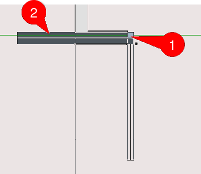
Select the wires created in steps 12 and 9 of this section on creating a fence, this will extrude the wires and create two new structures
Select the structures shown in the image above in the order indicated while holding the 'Ctrl' key
Select Arch Cut with plane tool Icon (
). Navigate to Combo View>Tasks> and under ‘Cut with
plane’ select the Front option from the drop-down list
Select ‘Ok’
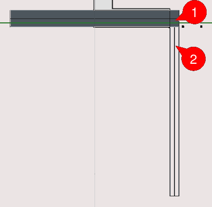
Select the structures shown in the image above in the order indicated while holding the ‘'Ctrl'’ key
Select the Arch Cut with plane tool Icon (
). Navigate to Combo View>Tasks> and under ‘Cut with
plane’ select the Front option from the drop-down list
Select ‘Ok’
Select the structures shown in the image above in the order indicated while holding the ‘Ctrl’ key
Select the Arch Cut with plane tool icon (
)Navigate to Combo View>Tasks> and under ‘Cut with plane’ select the Front option from the drop-down list
Select 'Ok'
Select the structures shown in the image above in the order indicated while holding the 'Ctrl' key
Select the Arch Cut with plane tool icon (
)Navigate to Combo View>Tasks> and under ‘Cut with plane’ select the Front option from the drop-down list
Select 'Ok'
Hide or delete the structures created in step 13 of creating a fence
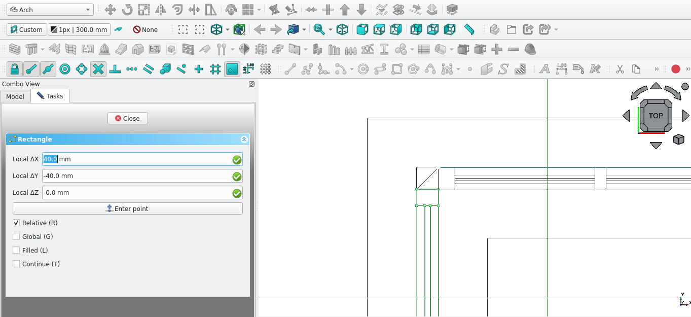
Creating reinforcement bars
Press 1 on the keyboard
Select the flat or planar part of the post and then select the Active plane icon (
)Press 'P' then 'Y' or select the Polyline tool icon (
)Select the vertex indicated in the image above
Navigate to Combo View>Tasks
For Local ΔX enter 0, for Local ΔY enter -40 mm, for Local ΔZ enter 0mm, then select Enter point
Press 'X', for Local ΔX enter 40 mm, then select Enter point
Press 'Y', for Local ΔY enter 1 mm, then select Enter point
Press 'X', for Local ΔX enter -39 mm, then select Enter point
Press 'Y', for Local ΔY enter 39 mm, then select Enter point
Press 'X', for Local ΔX enter -1 mm, then select Enter point
Select the newly created wire then press 'M' then 'V' or select the Move tool icon (
)Select the point indicated in the image above
Press 'N' to activate continue mode for the Move tool
Press 'Y'
For Local ΔY enter -307.5 mm then select Enter point
Press 'C'
Press 'Y'
For Local ΔY enter -127.5 mm then select Enter point
Press 'Esc'
Select the two newly created wires then select the Draft2sketch icon (
 )
)
Select the Structure tool
Select the newly created structure, Navigate to Combo View>Data and set the Y property to -1 to change normal of the structure if needed
Under Combo View>Data, set the Height property under structure to 0 and then set the Length property to 2615 mm
Creating Fence spikes
Press 'P' then 'Y' on the Keyboard or select the Polyline tool icon (
)Select the point labelled p1
Press 'X' on the keyboard, for Local ΔX enter -1.5 mm
For Local ΔX -3.7mm, for Local ΔY -16 mm
For Local ΔX enter -1.37, for Local ΔY 1.60, for Local ΔZ enter 0 mm then select Enter point
Press 'X' on the keyboard for Local ΔX enter -1.5 mm then select Enter point
For Local ΔX enter -1.5 mm, for local Local ΔY 1.75, for local Local ΔZ enter 0 mm then select Enter point (creating a closed loop, this will then end the polyline task
Select the newly created wire and then select the the Array tool icon (
)Navigate to Combo View>Tasks and under orthogonal array
Under Number of elements set the X property to 1, set the Y property to 18 and set the Z field to 1
Set all the X intervals fields to 0 mm
Set the Y field of the Y intervals to 14 mm and set the other two fields (z and x) to 0 mm
Set all the Z intervals to 0 mm
Select 'Ok'
Select the newly created Array and then select the Draft2Sketch tool icon (
)Select the newly created sketch and press 'M' then 'V' on the keyboard or select the Move tool icon (
)Navigate to Combo View>Tasks
Press ‘Z‘ on the keyboard
For Local ΔZ enter 100 mm, then select 'Ok'
Select the sketch moved in the previous step and then select the Structure tool icon (
)
With the newly create structure selected navigate to Combo View>Data and enter 1800 mm for the height property of the structure
Select the structure in Combo View>Model and press ‘F2’ then enter the name ‘spikes’
Press 6 on the keyboard
Select the face shown in the image above then select the Active plane icon (
)
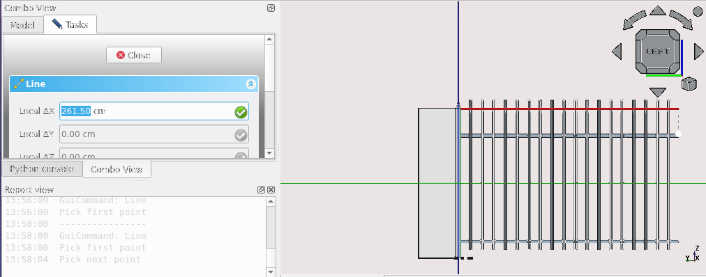
Press 'L' then 'I' on the keyboard or select the Line tool Icon (
 )
)
Navigate to Combo View>Tasks
Press 'X' on the keyboard and enter 261.50 cm or 2615 mm for Local ΔX
Press 'Enter' on the keyboard
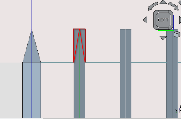
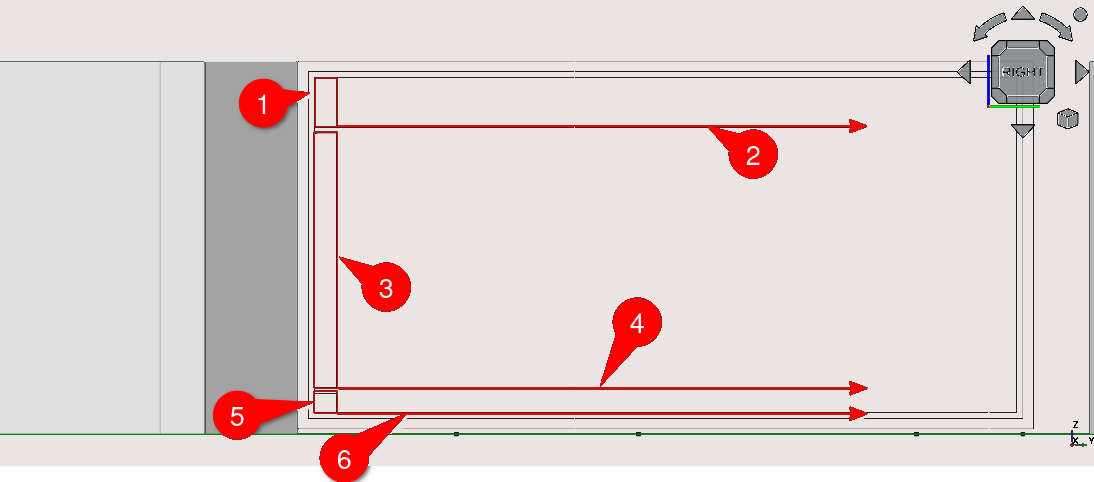
Create two wires in the shape of the highlighted red lines shown above. Hint: use the Polyline tool and snaps, remembering to go anticlockwise when drawing the polyline
Select one of the wires then select the Array tool icon (
)
Navigate to Combo View>Tasks and go to orthogonal array
Under Number of elements set the X property to 1, set the Y property to 18 and set the Z field to 1
Set all the X intervals fields to 0 mm then press 'Enter' on the keyboard
Set the Y field of the Y intervals to 14 mm and set the other two fields (Z and X) to 0 mm
Repeat the same steps from 25 to 29 for creating a spike on the other wire
Select the array created in step 28 and select the Draft2sketch tool icon
Select the other array created in number 30 of creating a spike and select the Draft2sketch icon (
)Select both newly created sketches then select the Structure tool
Press 2 on the keyboard
Select the Active plane icon (
) and Navigate to Combo View>Tasks and select Top (XY)Select both newly created structures under Combo View>Model (be sure to hold 'Ctrl' while selecting)
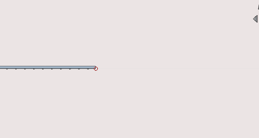
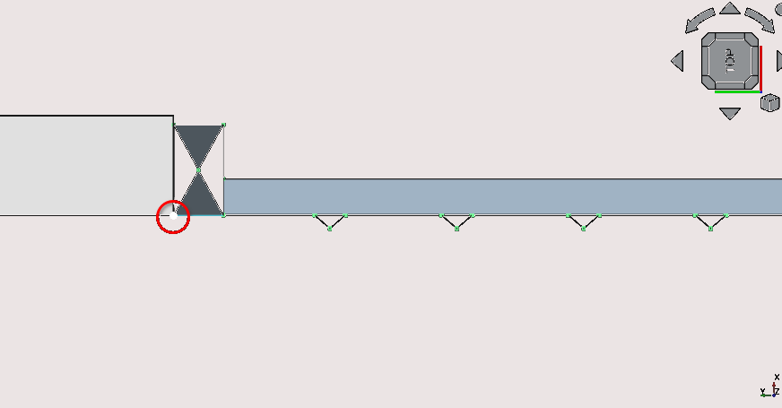
Press 'M' then 'V' or select the Move tool icon (
)Select the point indicated above using snap mid point
Press 'X' on the keyboard
Navigate to Combo View>Tasks and under move, for ΔX enter 500 mm, unselect continue then press 'Enter' on the keyboard
While holding 'Ctrl' select one of recently moved structures then select the structure labelled ‘spike’ and select the Arch Remove tool icon (
 )
)Repeat the previous step with the other structure and the structure labelled ‘spike’
While holding 'Ctrl' Select the item labelled reinforcement then the item labelled ‘Spike’ then select the Arch add tool icon (
 )
)While holding 'Ctrl' select the item labelled ‘Post’, the item labelled ‘Spike’ then select the Arch add tool icon
Rename the item labelled ‘spike’ by selecting it under Combo View>Model and pressing F2, then enter the name ‘fence section’
Part 5: creating The boundary using a section of fence
Press 'L' then 'I' on the keyboard or select the Line tool icon (
) and then select the point highlighted abovePress 'Y' and under Combo View>Tasks input -18745 mm
Press 'Enter'
While holding 'Ctrl' select the object labelled ‘fence section’, select the newly created line and then select the Path Array tool icon (
 )
)With the newly created path array object selected, Navigate to Combo View>Data, then go to position and select the small grey arrow. For the X property of Position enter 4649.71 cm or 46497.1 mm and for the Y property enter 2511.44cm or 25114.4 mm
Under Align set the Extra translation Y property to 100 cm or 1000 mm then set the Offset property to 272.50 cm or 2725 mm
-2136.00
Select the item labelled ‘fence section’ then select the Clone tool icon (
 )
)Select the newly created clone and press 'M' then 'V' on the keyboard or select the Move tool icon (
) (remember to select the starting point shown in the image
above)Press 'N' on the keyboard
Press 'Y' on the keyboard, then enter -2136.00 for Local ΔY Press 'X' on the keyboard, then enter -10 for Local ΔX
Press 'Esc' to end the task
-2136.00
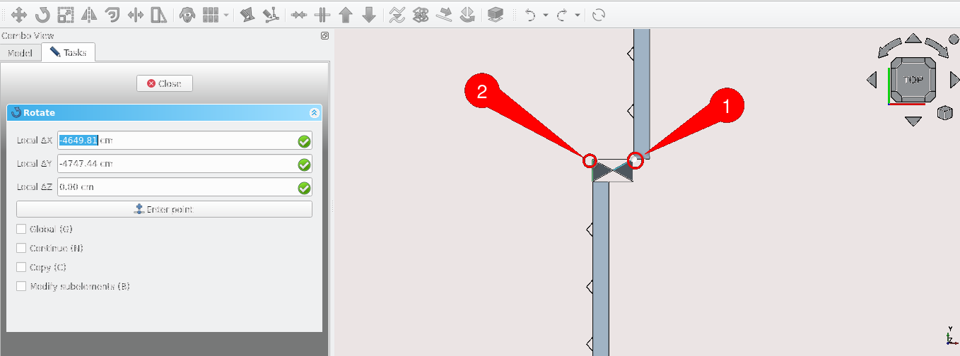
Select the clone then Press 'R' then O or select the Rotate tool icon (
 ) and select the clone at the points indicated above in order
enter 90 in Combo View>Tasks under rotate and press 'Enter'
-2136.00
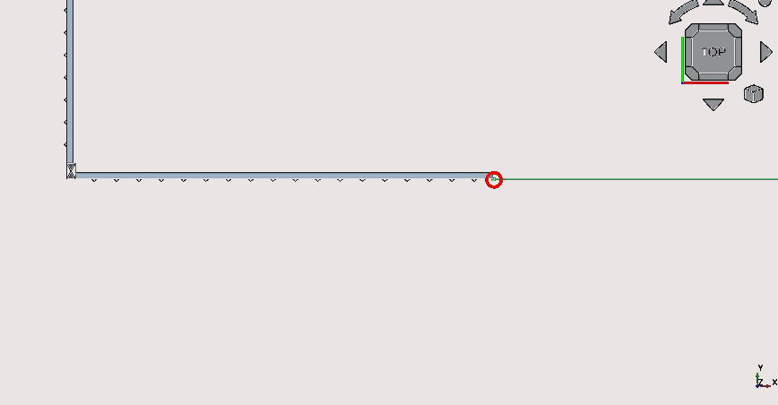
Press 'L' then 'I' on the keyboard or select the Line tool icon (
) and select the point shown abovePress 'X' and for Local ΔX enter 3471cm or 34710 mm
Press 'Enter' or select Enter point
Select the clone, select the newly created line then select the Path Array tool icon (
)
Navigate to Combo View>Model and select the Structure labelled fence section
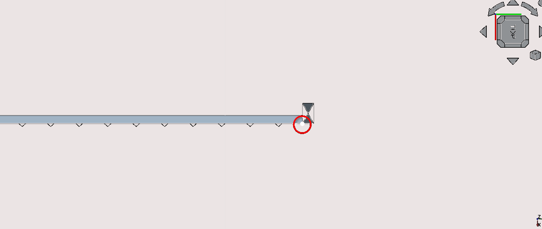
Select the clone tool icon (
)Select the newly created clone then press 'R' then O or select the rotate tool icon (
)
Select the points as shown in the image above(one being an endpoint and the other being a mid point)
Navigate to Combo View>Tasks and input 180 in under Rotation
Press 'Enter'
Select the rotated clone and press 'M' then 'V' or select the move icon (
)Enter 3840.60 cm or 38406 mm for Local ΔX
Press 'Enter'
Select the moved clone then select the clone tool icon
Select the clone then press 'M' then 'V' on the keyboard or select the Move tool icon (
), select anywhere on the clone then press y
Press 'L' then 'I' and select the point shown in the image above
press 'Y' and for Local ΔY enter 8118.8 mm then press 'Enter'
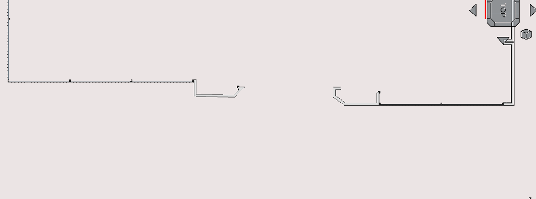
While holding the 'Ctrl' key select the newly created clone in the previous step, select the newly created line then select the Path Array tool icon (
)Select the newly created path array and Navigate to Combo View>Data
Set the count property to 3, under Extra translations set the x property to 46398.1 mm and y property to 26114.4
Navigate to combo View>Model and select the item labelled fence section, select the grey arrow next to the object then select the item labelled post
With the structure item labelled ‘post’ selected select the Clone tool icon (
 )
)With the newly created clone selected press 'M' then 'V' on the keyboard or select the Move tool icon (
)Select the point on the object as shown in the image above
Select the point in the image displayed above
Part 6: creating the front gate
Creating the front entrance walls
Press ‘P’ then 'Y' or select the Polyline tool icon (
)
Select point 3 and press 'Y'
Navigate to Combo View>Tasks
Input 305.4 mm, for Local ΔY and enter 30.54 mm then press 'Enter'
Press 'Y', for Local ΔX enter 437.3 mm and for Local ΔY enter -448.6 mm
Press 'Y' and enter -1770.5 mm for Local ΔY then press ‘Enter’
Press 'X', for Local ΔX enter 747.8 mm then press ‘Enter’.
Press 'Esc' or select close to end the task
Select the newly created wire then press 'W' then 'A' or select the Wall tool icon
With the newly created wall selected navigate to Combo View>Data
Under Wall set the Align property to left, set the Height property to 1800 mm and set the Width property to 110 mm
Select the newly created Wall in Combo View>Model and rename it by pressing the ‘F2’ key and entering ‘front gate wall 1’
Press 'P' then 'Y' or select the Polyline tool icon (
)
Select point 2 and press 'X'
Navigate to Combo View>Tasks
305.4 mm, for Local ΔX enter 573.8 mm then press 'Enter'
Press 'Y' and enter Local ΔX enter 437.3 mm and for Local ΔY enter -448.6 mm
Press 'Y' and enter -1499.1 mm for Local ΔY then press 'Enter'
For Local ΔX enter -358.2 mm, for Local ΔY enter -497.5 mm then press 'Enter'
Press 'X' ,For Local ΔX enter -431.2 mm then press 'Enter'
Press 'Y' then for Local ΔY enter 340 mm
Press 'Esc' or Select close in Combo View>Tasks to end the task
Select the newly created wire then press 'W' then 'A' or select the Wall tool icon (
)
With the newly created wall selected navigate to Combo View>Data
Under Wall set the Align property to left, set the Height property to 1800 mm and set the Width property to 110 mm
Select the newly created Wall in Combo View>Model and rename it by pressing the 'F2' key and entering ‘front gate wall 2’
Creating the front gate
Press '3' on the keyboard to set the view to the right view
Select the current working plane icon and navigate to Combo View>Tasks
Under Working plane setup select align to view
You may hide the path array by selecting it and pressing the space bar on the keyboard
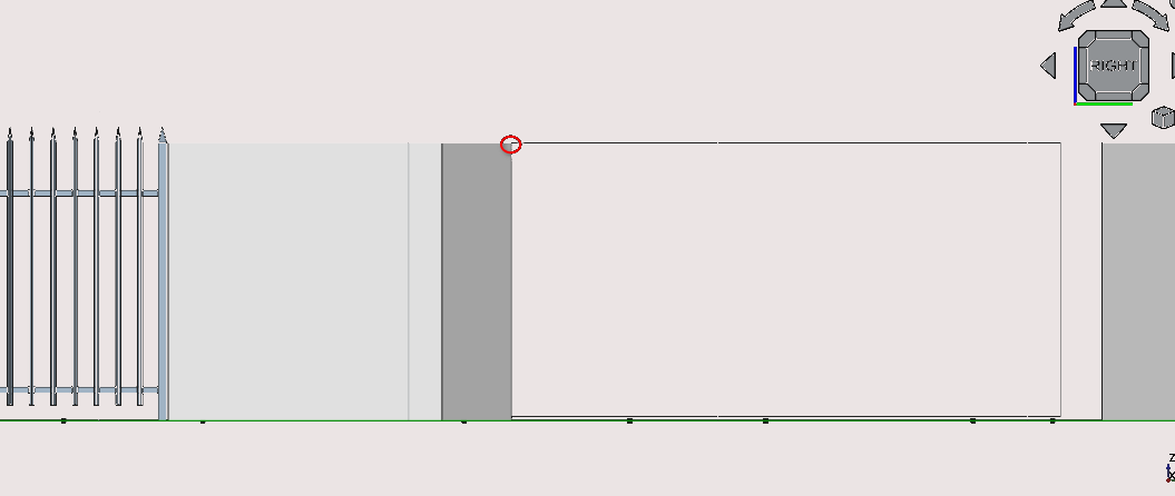
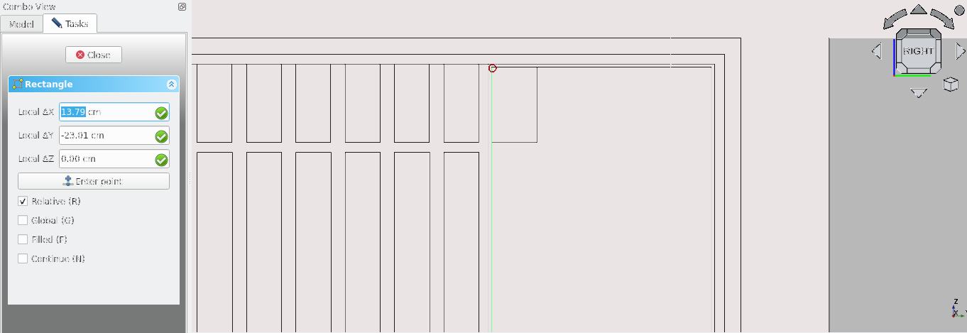
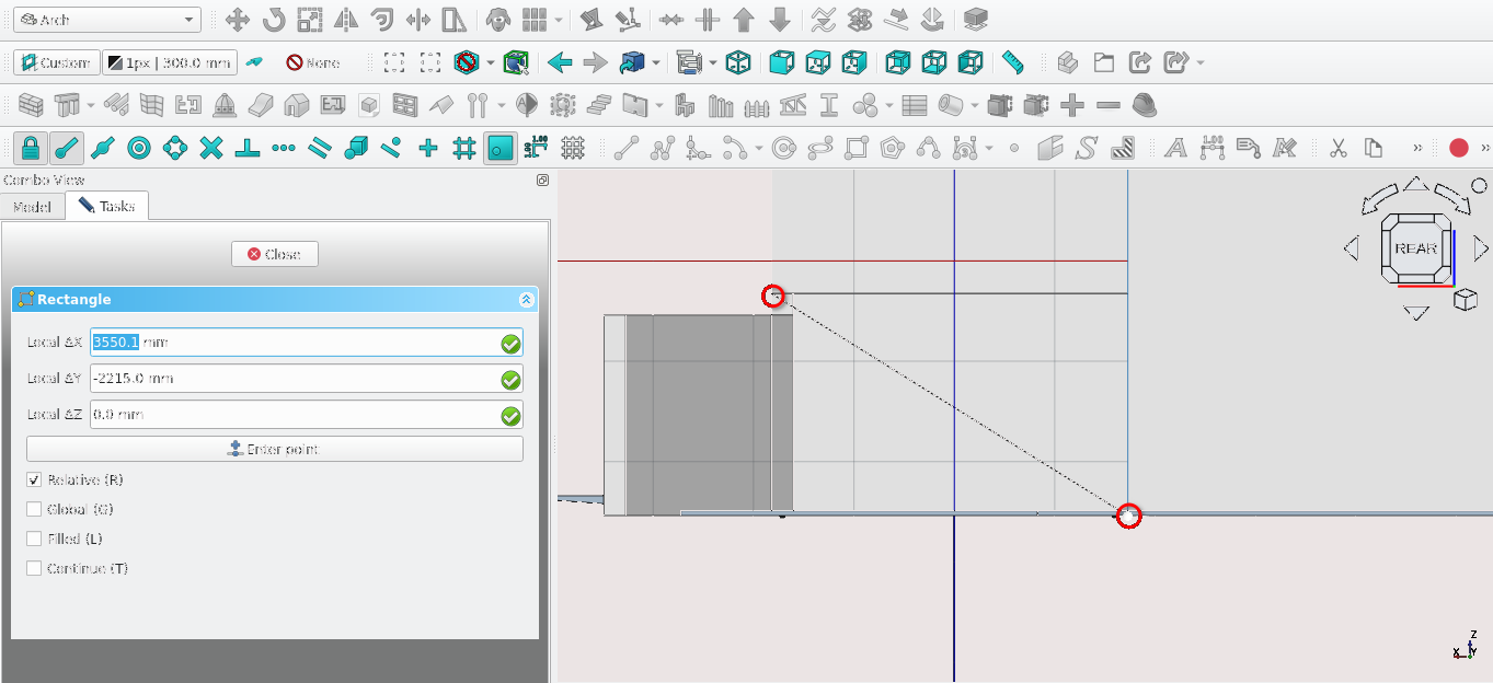
Press 'R' then 'E' or select the Rectangle tool icon (
) and select the vertex as shown in the image above
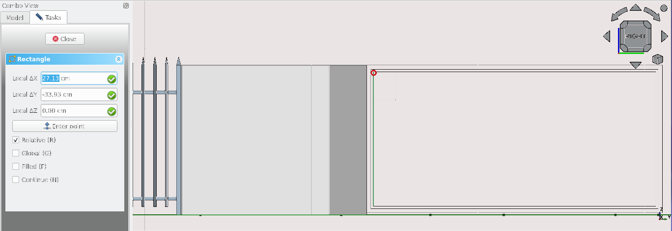
For Local ΔX enter 3550 mm and for Local ΔY enter -1775mm
Select the newly created rectangle then select the Offset tool icon (
 ) or press 'O' then 'S' on the keyboard. Place the cursor within
the rectangle and enter 50 mm, then press 'Enter' on the
keyboard
) or press 'O' then 'S' on the keyboard. Place the cursor within
the rectangle and enter 50 mm, then press 'Enter' on the
keyboardSelect the newly offset rectangle and offset it by 30 mm inwards
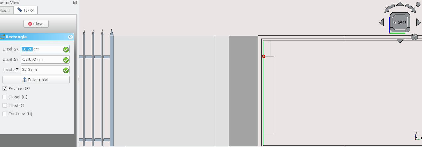
Press 'R' then 'E' on the keyboard or select the Rectangle tool icon (
)Navigate to Combo View>Tasks
For Local ΔX enter 106.3 mm, for Local ΔY enter -240 mm
Press 'Enter' on the keyboard after each entry
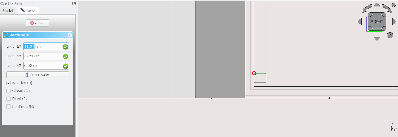
Press 'R' then 'E' or select the Rectangle tool icon (
) and select the vertex as shown in the image above
For Local ΔX enter 106.3 mm, for Local ΔY enter -12250 mm
Press 'Enter' on the keyboard after each entry
With the newly created rectangle selected press 'M' then 'V' or select the Move tool icon (
)Select the same vertex shown in the image above then press 'Y' on the keyboard
Navigate to Combo View>Tasks
For Local ΔY enter -30 mm then press 'Enter' on the keyboard
Press 'R' then 'E' or select the Rectangle tool icon (
) and select the vertex as shown in the image above
For Local ΔX enter 107.3 mm, for Local ΔY enter -90 mm
Press 'Enter' on the keyboard after each entry
With the newly created rectangle selected press 'M' then 'V' or select the Move tool icon (
)Select the same vertex shown in the image above then press 'Y' on the keyboard
Navigate to Combo View>Tasks
For Local ΔY enter -30 mm then press 'Enter' on the keyboard
Press 'L' then 'I' on the keyboard or select the Line tool icon (
) and then select the point shown abovePress 'X'
For Local ΔX enter -2561.4 mm, then press 'Enter' on the keyboard
Select the newly created line then Press 'M' then 'V' on the keyboard or select the Move tool icon (
)Press 'Y'
Press 'N'
Press 'C'
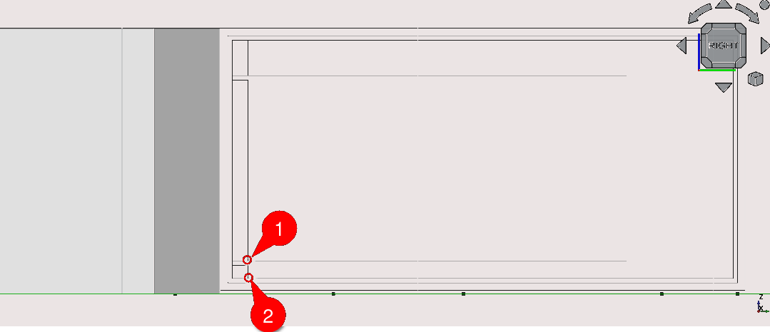
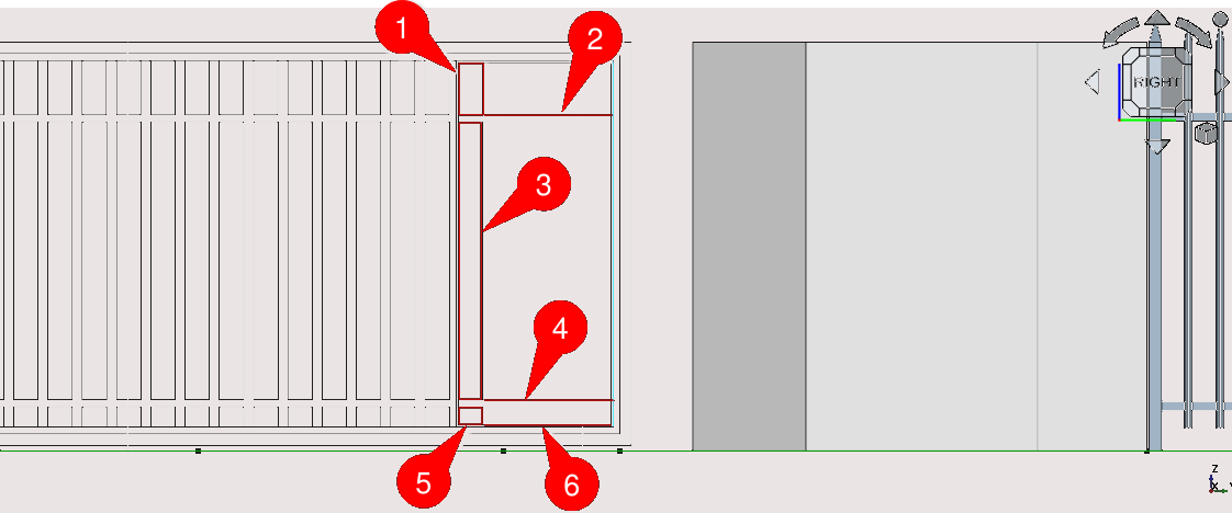
Select the point indicated in the image below (1)
Press 'C'
Select the point indicated in the image below (2)
Select the rectangle (1) then select the line (2) then select the Path Array tool icon (
), select the newly created array and navigate to Combo
View>Data then set the End Offset to 106.3 mm then set the
Start Offset to -106.3 mmSelect the rectangle (3) then select the line (4) then select the Path Array tool icon (
), select the newly created array and navigate to Combo
View>Data then set the End Offset to 106.3 mm then set the
Start Offset to -106.3 mmSelect the rectangle (5) then select the line (6) then select the Path Array tool icon (
), select the newly created array and navigate to Combo
View>Data then set the End Offset to 106.3 mm then set the
Start Offset to -106.3 mm
Press 'R' then 'E' or select the Rectangle tool icon (
) and select the vertex as shown in the image aboveFor Local ΔX enter -691.2 mm then for Local ΔY enter -1615 mm
Press 'Enter' twice
Select the newly created rectangle then select the Offset tool icon (
) or press 'O' then 'S' on the keyboard. Place the cursor within
the rectangle and enter 10 mm, then press 'Enter' on the
keyboard
Press 'R' then 'E' or select the Rectangle tool icon (
) and select the vertex as shown in the image aboveSelect the newly created rectangle then press 'M' then 'V' or select the Move tool icon (
For Local ΔX enter -107.3 mm then for Local ΔY enter -1225 mm
Press 'Enter'

Press 'R' then 'E' or select the Rectangle tool icon (
) and select the vertex as shown in the image aboveSelect the newly created rectangle then press 'M' then 'V' or select the Move tool icon (
)For Local ΔX enter 107.3 mm then for Local ΔY enter 80 mm
Press 'Enter' twice
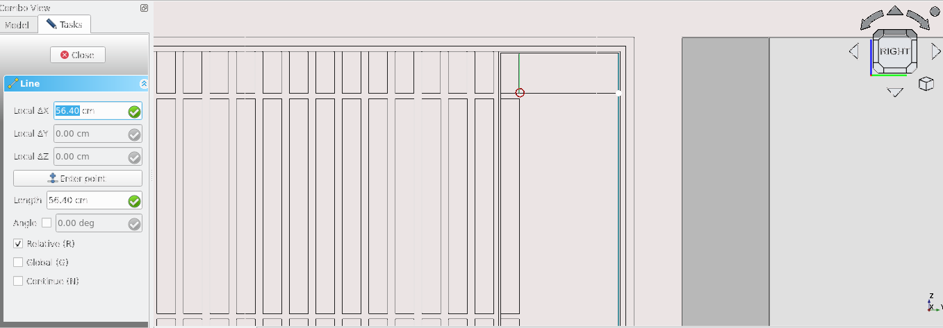
Press 'L' then 'I' on the keyboard or select the Line tool icon (
) then select the point shown abovePress 'X' then Navigate to Combo View>Tasks
Under Line enter 564 mm
Press 'Enter' on the keyboard or select Enter point
Label diagram
Select the newly created line then Press 'M' then 'V' on the keyboard or select the Move tool icon (
)Press 'Y'
Press 'N'
Press 'C'
Select the point indicated in the image above (1)
Press 'C'
Select the point indicated in the image above (2)
Select the rectangle (1) then select the line (2) then select the Path Array tool icon (
), select the newly created array and navigate to Combo
View>Data then set the End Offset to 107.3 mm and then set
the Start Offset to -107.3 mm set the count property to 4Select the rectangle (3) then select the line (4) then select the Path Array tool icon (
), select the newly created array and navigate to Combo
View>Data then set the End Offset to 107.3 mm and then set
the Start Offset to -107.3 mm and set the count property to 4Select the rectangle (5) then select the line (6) then select the Path Array tool icon (
), select the newly created array and navigate to Combo
View>Data then set the End Offset to 107.3 mm and then set
the Start Offset to -107.3 mm, set the count property to 4Delete the rectangles highlighted in the image below and unhide the rectangles used as bases for the path array in the last two steps
Hide the lines used to create the path arrays
Press '3' on the keyboard to go to the right view
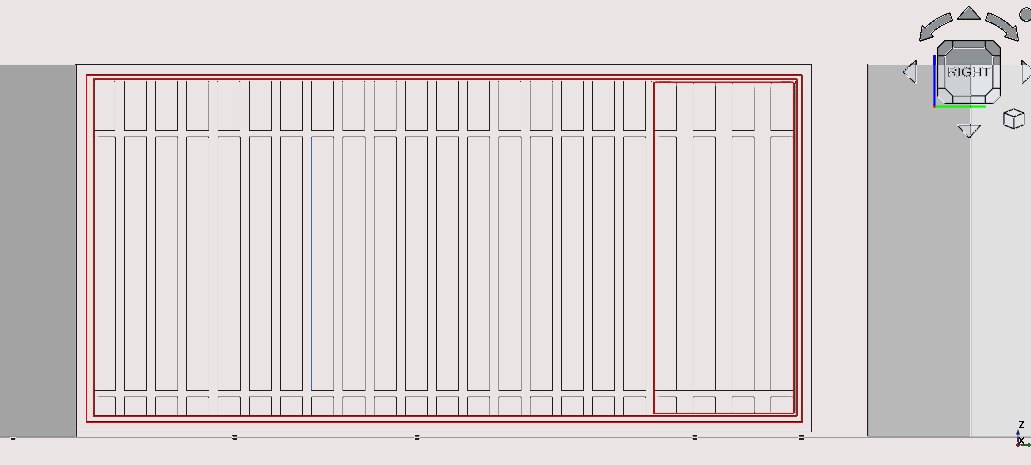
Press 'Shift' then 'B' or to box select and select the 2D elements created steps 29 to 91 of part 6: creating the front gate
Select the Draft2sketch tool icon (
)Press 'Delete' on the keyboard to delete the items used to create the sketch
With the newly created sketch selected press 'W' then 'N' on the keyboard or select the Window icon (
 )
)
Double-select the newly created window under Combo View>Model
Select default under components then select edit
Select Name field and enter main gate, keep the type as frame, leave the wires as is, set the Thickness property to 30 mm, leave the offset field as is and leave the opening and Hinge as is
Select Create/update component
Under components select the default item then select remove
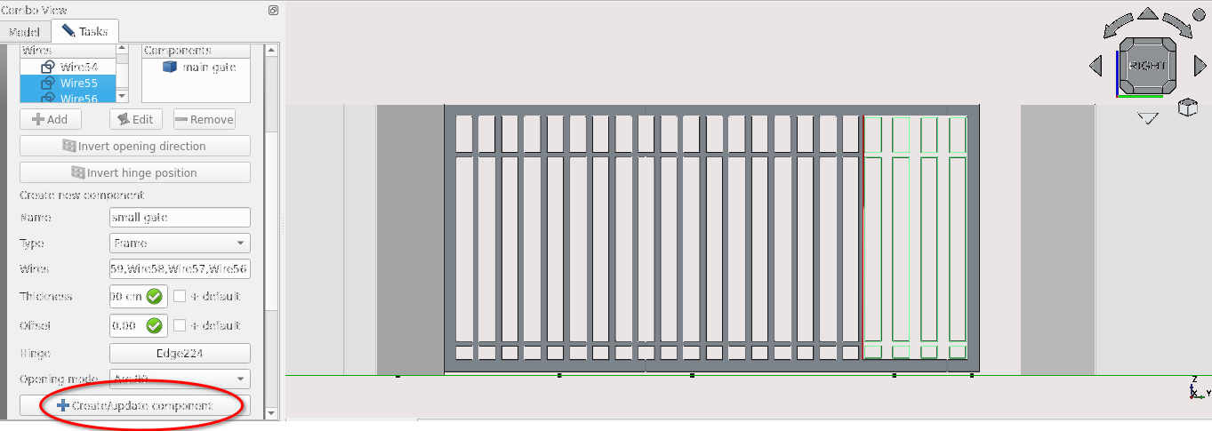
Select the add icon in Combo View>Tasks under window element
Select the Wires under Create new component then shown in the image above
Set the name property to small, leave the Type property as is, set the thickness to 20 mm leave the Offset as is, select the wire highlighted in the image above then select the hinge field, making sure to set the opening mode to arc 90
Select Create/update component then scroll up and select close or press 'Esc' on the keyboard
Select the newly created window in Combo View>Model and press F2, rename this window as ‘front gate’
Press 1 on the keyboard
Select the active plane icon () then under combo view> Tasks and select Top(XY)
Navigate to Combo View>Model and select the sketch base on the item labelled front gate and press 'M' then 'V' or select the Move tool icon (
)Navigate to Combo View>Tasks, press ‘X’, for Local ΔX enter 8804.6 mm then press 'Enter'
Toggle the continue mode on by pressing 'N' on the keyboard if it is not already on
Press 'Y'
For Local ΔY enter 134.8 mm, then press 'Esc' on the keyboard to end the task
Press 2 to go to the top view
Zoom out using the mouse scroll wheel and select the items shown in the image below, then option click and select Utilities>add new name group and enter ‘boundary’ in the text prompt then press 'Enter'
You can now Navigate to Combo View>Model> boundary and expand it by selecting the the grey arrow next to the text you can also toggle weather all these items in the group are visible by selecting the group and pressing the space bar
Part 7: creating the walls of the building
Creating the exterior walls
Pan to point a
Press 'P' then 'Y' on the keyboard or select the polyline icon (
)
Join points a to g by using Point snap and the polyline tool (you can confirm the names of the points by selecting them and looking at the list of items in Combo View>Models>points)
Navigate to Combo View>Model and select the newly created polyline and press 'W' then 'A' on the keyboard or select the Wall tool icon (
)
Navigate to Combo View>Model and select the newly created wall object
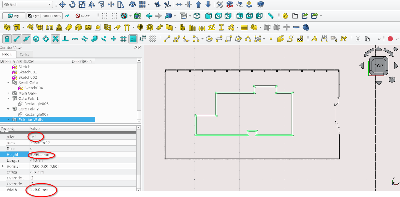
Press 'F2' and rename it to ‘Exterior Walls’
With the newly created wall selected navigate to Combo View>Model, next to the align property select the drop-down menu then select Left
Go to the Width property and type in 220 mm
Creating the interior walls
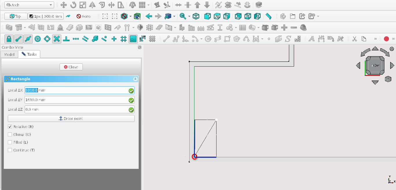
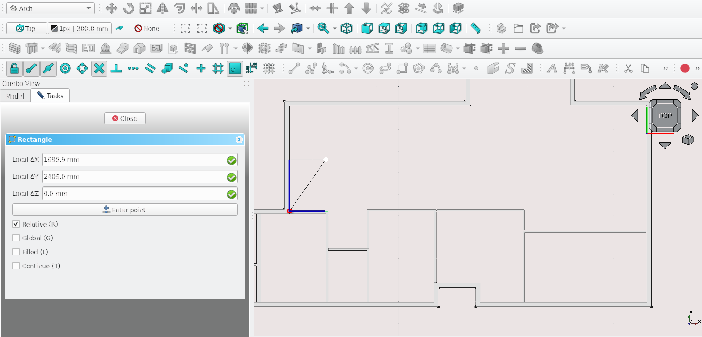
Press 'R' then 'E' on the keyboard or select the Rectangle tool icon (
)Select the point highlighted in the image above, For Local ΔX enter 1010 mm and for Local ΔY enter 1690 mm
Navigate to Combo View>Model Select the newly created rectangle
Press 'D' then 'N' or select the Downgrade icon (
 )
)Navigate to Combo View>Model and select the edges highlighted in dark blue (shown above) while holding the 'Ctrl' key
Release the 'Ctrl' key and press the 'Delete' key, then select the remaining edges while holding the 'Ctrl' key and then release the 'Ctrl' key
Press 'U' then 'P' on the keyboard or select the Upgrade icon (
 )
)With the newly created object selected press 'W' then 'A' on the keyboard or select the Wall tool icon (
)With the newly created wall selected navigate to Combo View>Model, then go to the Align property and select the drop-down menu and then select Left
Go to the Width property and type in 110 mm
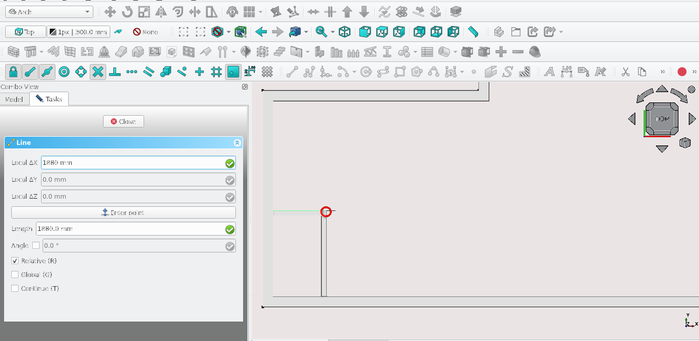
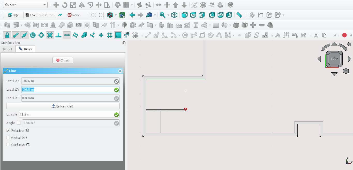
Press 'L' then 'I' or select the line tool icon (
)Select the point highlighted above
Navigate to Combo View>Tasks
Press 'X' on the keyboard
Set the value of Local ΔX to 1880 mm and select Enter point
Toggle on the Snap Extension icon (
 )
)Hover the cursor over the point above and move it upwards until a dashed line appears from the highlighted point to the desired endpoint of your new line (in this case, the interior part of the Exterior wall)
Press 'Y' on the keyboard
Move the cursor and select the inward part of the exterior wall
For Local ΔY enter -4100 mm
Navigate to Combo View>Model and select the newly created line
Press 'W' then 'A' on the keyboard or select the Wall tool icon (
)Select the newly created wall under Combo View>Data
Set the Align property to Right then set the Width property to 110 mm
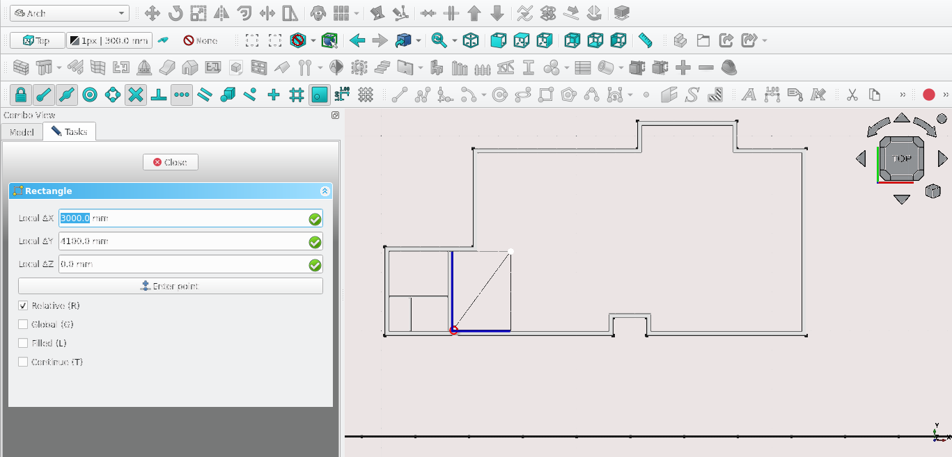
Press 'R' then 'E' on the keyboard or select the Rectangle tool icon (
)Select the point highlighted in the image above
Navigate to Combo View>Tasks. Set the value of Local ΔX to 3000 mm and the value of Local ΔY to 4100 mm
Select Enter point or press 'Enter'
Navigate to Combo View>Model
Select the newly created rectangle and select the Downgrade icon (
) or press 'D' then 'N' on the keyboardIn Combo View>Model hold 'Ctrl' while selecting the edges highlighted in dark blue in the image above
Press 'Delete'
Select Edge overlapping with the wall
Press 'T' then 'R' or select the Trimex tool icon (
 )
)Hold 'Ctrl' to use snaps
Select the vertex where wall and line overlap
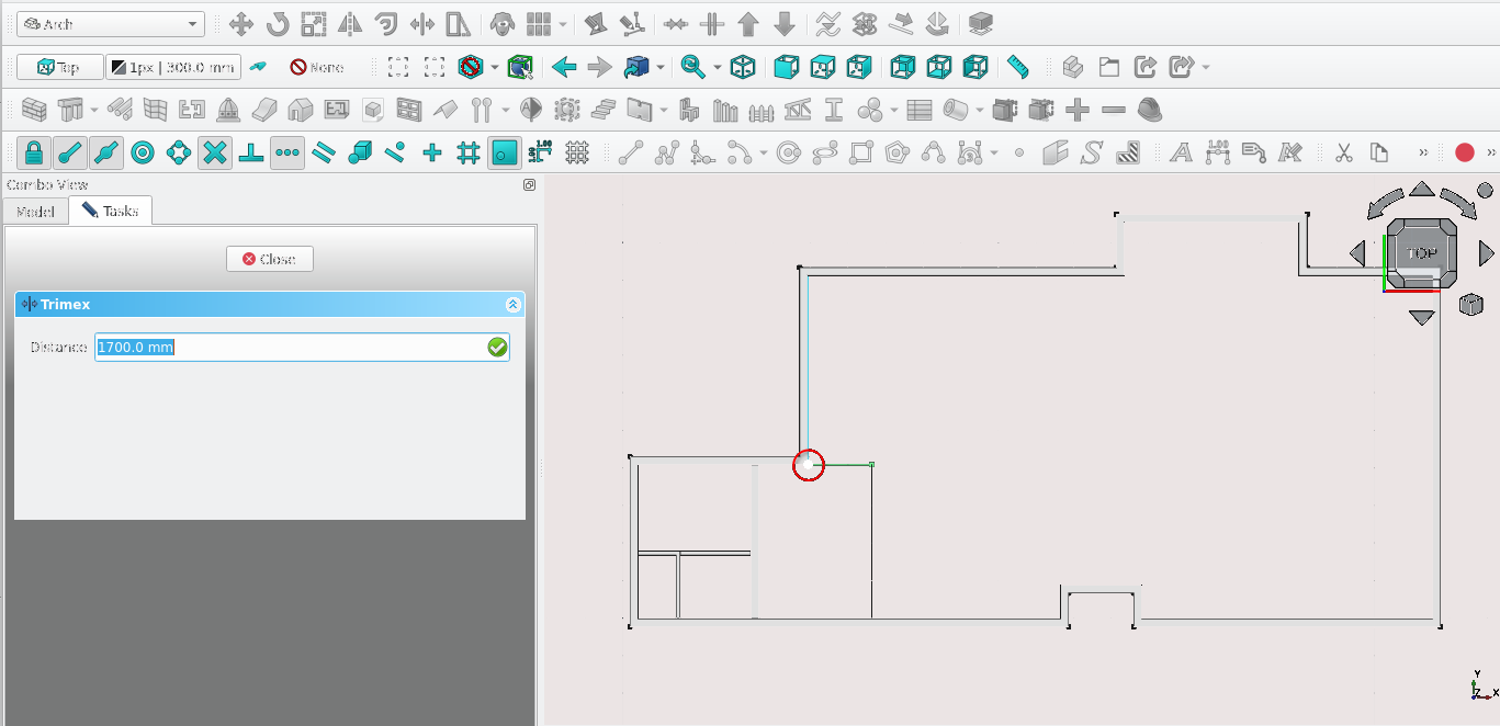
Navigate to Combo View>Task
Select the starting point (the point highlighted in red above)
Select the edges left over after deletion while Holding the 'Ctrl' key then release the 'Ctrl' key
Press 'U' then 'P' on the keyboard or select the Upgrade icon (
)Press 'W' then 'A' on the keyboard or select the Wall tool icon (
)With the newly created wall selected navigate to Combo View>Data, next to the align property select the drop-down menu and select Left
Go to the Width property and type in 110 mm
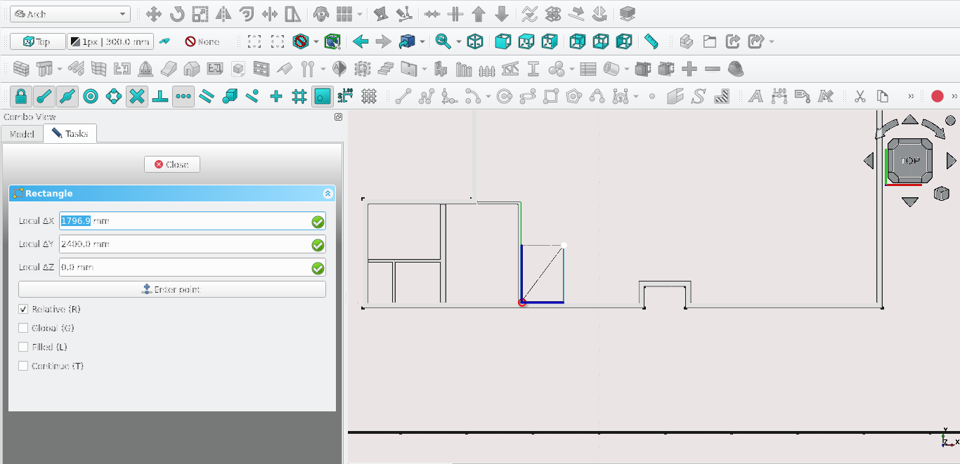
Press 'R' then 'E' or select the Rectangle tool icon (
)Select the point shown in the image above
For Local ΔX enter -1796.9 mm
For Local ΔY enter 2400 mm
Select Enter point
Navigate to Combo View>Model Select the newly created rectangle
Press 'D' then 'N' or select the Downgrade tool icon (
)Select the edges highlighted in dark blue shown in the image above while holding the 'Ctrl' key
Release the 'Ctrl' key then press 'Delete'
While holding 'Ctrl' select the remaining edges then release the 'Ctrl' key and select the Upgrade tool icon (
) or press 'U' then 'P'
Press 'W' then 'A' on the keyboard or select the Wall tool icon (
)With the newly created wall selected navigate to Combo View>Data, then go to the Align property, select the drop-down menu and then select Left
Go to the Width property and enter 110 mm
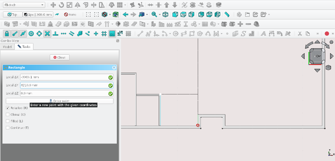
Press 'R' then 'E' or select the Rectangle tool icon (
)Select the point highlighted in red shown in the image above
Navigate to Combo View>Tasks
For Local ΔX enter -3003.1 mm
For Local ΔY enter 4210.0 mm
Select Enter point or press the 'Enter' key
Navigate to Combo View>Model and select the newly created rectangle
Press 'D' then 'N' or select the Downgrade tool icon (
)Navigate to Combo View>Model, select the newly created edge highlighted in Dark blue (in the image below) while holding 'Ctrl'
Press 'Delete' on the keyboard
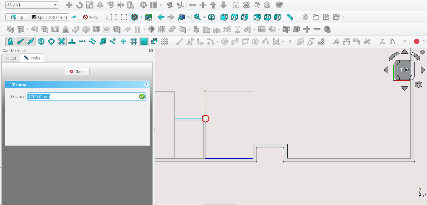
Navigate to Combo View>Model and select the edge highlighted in light green
Press 'T' then 'R' on the keyboard or select the Trimex tool icon (
)Hold 'Ctrl' and 'Alt' while selecting the point highlighted above
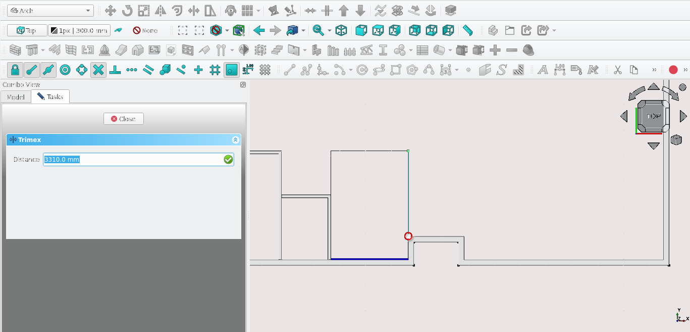
Select the edge highlighted in light blue in the image above
Press 'T' then 'R' or select the Trimex icon (
)While holding 'Ctrl', select the Vertex shown above
Press 'U' then 'P' or select the Upgrade icon (
)With the wire still selected press 'W' then 'A' on the keyboard or select the Wall tool icon (
)With the newly created wall selected navigate to Combo View>Model, next to the align property select the drop-down menu and then select Left
Go to the Width property and enter 110 mm
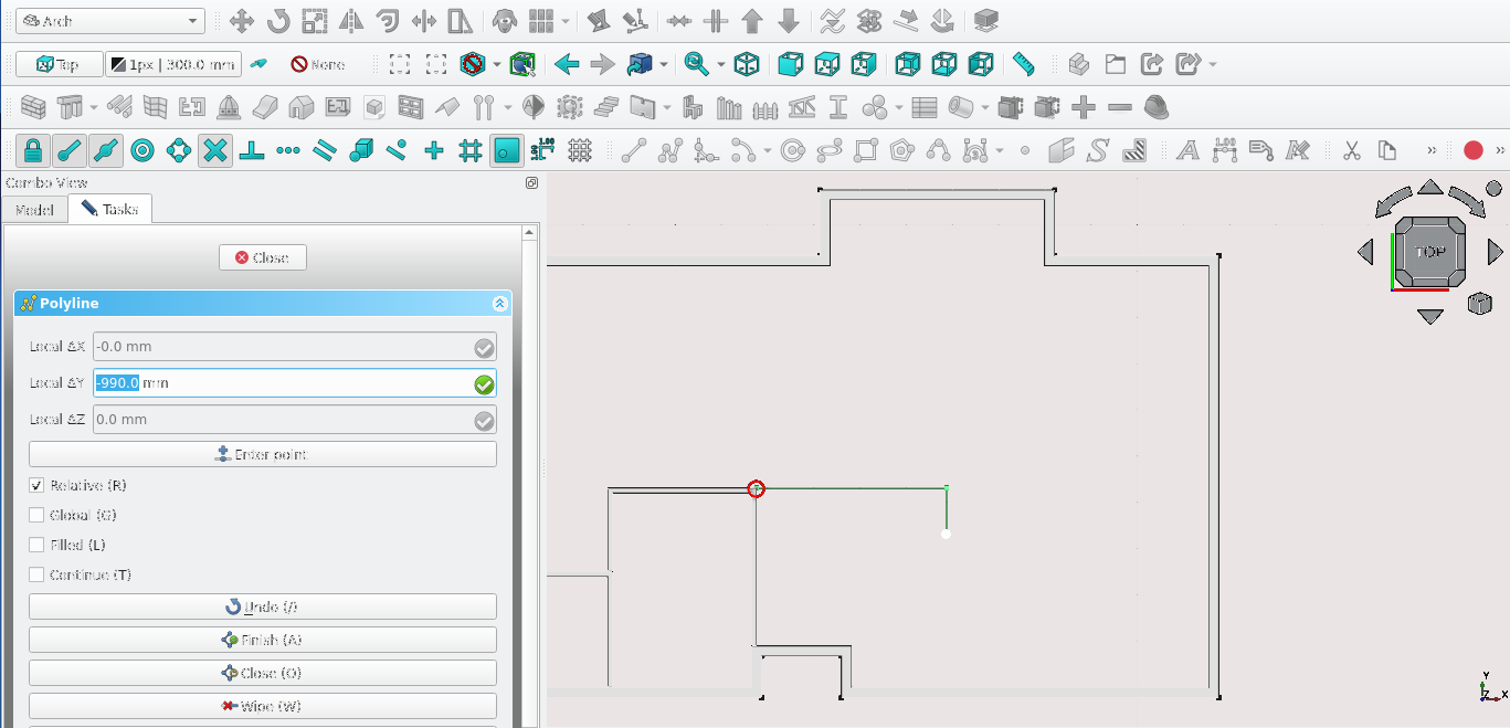
Press 'P' then 'Y' or select the polyline tool(
)Select the point highlighted in red
Press 'X'
Select Enter point
Press 'Y' on the keyboard
For Local ΔY enter -990 mm
Select Enter point
Navigate to Combo View>Model and select the newly created wire
Press 'W' then 'A' on the keyboard or select the Wall tool icon (
)With the newly created wall selected navigate to Combo View>Model, next to the align property, select the drop-down menu and then select Right
Go to the Width property and enter 110 mm
Press 'R' then 'E' or select the Rectangle tool icon (
)Select the two points highlighted in the image above
Navigate to Combo View>Model
Select the newly created rectangle
Select the Downgrade icon (
) or press 'D' then NNavigate to Combo View>Model and select the edges highlighted in dark blue (shown above) while holding 'Ctrl'
Release the 'Ctrl' key
Press 'Delete' on the keyboard
While holding 'Ctrl' select the remaining edges then release the 'Ctrl' key
Press 'U' then 'P' or select the Upgrade tool icon (
)Navigate to Combo View>Model and select the newly created wire
Press 'W' then 'A' on the keyboard or select the Wall tool icon (
)With the newly created wall selected navigate to Combo View>Model, next to the align property, select the drop-down menu and then select Right
Go to the Width property and enter 110 mm
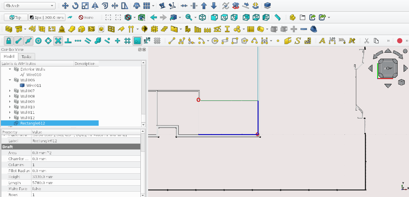
Press 'R' then 'E' or select the Rectangle tool icon (
)
Select the point highlighted in red shown in the image above
Navigate to Combo View>Tasks and go to Rectangle
For Local ΔX type in 4110 mm
For Local ΔY type in 2405.0 mm
Navigate to Combo View>Model, select the newly created rectangle and select the Downgrade tool icon (
) or press 'D' then ‘N’Navigate to Combo View>Model and select the wires highlighted in blue while holding 'Ctrl'
Release the 'Ctrl' key and press the 'Delete' key
Navigate to Combo View>Model select the remaining edges while holding 'Ctrl'
Select the Upgrade icon (
) or press 'U' then 'P'
Navigate to Combo View>Model, select the newly created wire then press 'W' then 'A' on the keyboard or select the Wall tool icon (
)With the newly created wall selected navigate to Combo View>Model, next to the align property, select the drop-down menu and then select Left
Go to the Width property and enter 110 mm
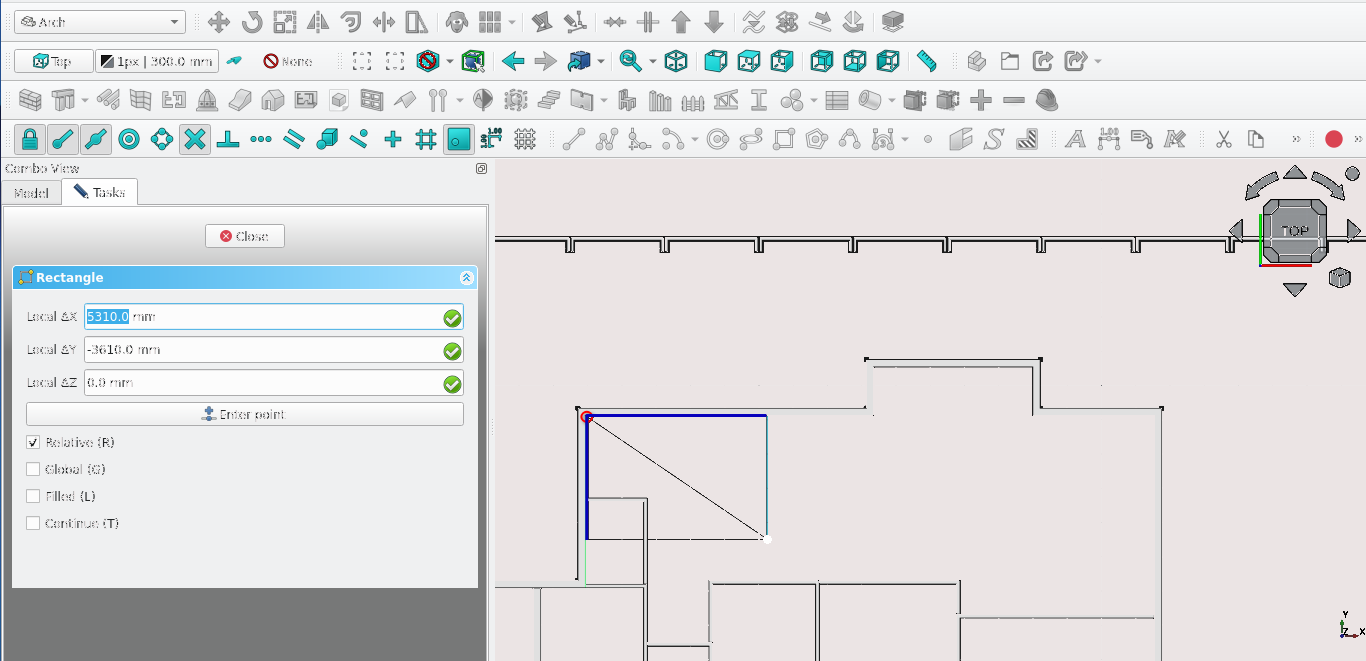
Press 'R' then 'E' or select the Rectangle tool icon ((
)Navigate to Combo View>Tasks and go to Rectangle
For Local ΔX type in 5310 mm and for For Local ΔY enter -3610 mm
Navigate to Combo View>Model and select the newly created Rectangle
Select the Downgrade tool icon (
) or press 'D' then ‘N’Select the edges highlighted in dark blue and while holding the 'Ctrl' key, release the 'Ctrl' key and press the ‘Delete’ key
Press 'L' then 'I' on the keyboard or select the Line tool Icon(
) then select the point labelled 1 in the image shown abovePress 'X' on the keyboard to restrict its creation to the x-axes
Select the second point shown above labelled 2 in the image shown above
Select the newly created line
Press 'W' then 'A' on the keyboard or select the Wall tool icon (
)Navigate to Combo View>Data, under Wall set the Align Property to Right
Go to the Width property and enter 110 mm
Press 'P' then 'Y' on the keyboard or select the Polyline tool icon (
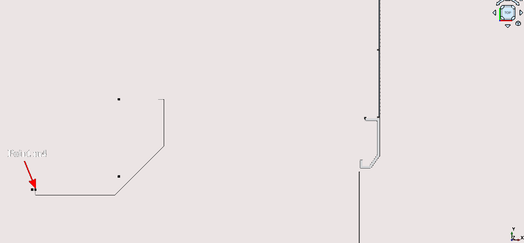
)Select the point labelled m4 (you can confirm the position of an item by hovering your cursor over it in Combo View>Model
Select the point labelled m4
Navigate to Combo View>Tasks>Polyline
For Local ΔX enter -610.4, for Local ΔY enter -220 mm
Select Enter point or press 'Enter' on the keyboard
Press 'X' to restrict the segment of the polyline to the x-axes
For Local ΔX type in 3154.5 mm
For Local ΔX enter 1935.6 mm and for Local ΔY enter 1935.5 mm
Press 'Y'
For Local ΔY enter 1863.3 m
For Local ΔX enter -220 mm
Select Enter point or press 'Enter'
Select the newly created polyline
Press 'W' then 'A' on the keyboard or select the Wall tool icon (
)With the newly created wall selected Navigate to Combo View>Data and under wall select the Align field then select Right
Go to the Width property and enter 110 mm
Note the image above has hidden other elements such as the previously created walls: you may do this by selecting the items you wish to hide under Combo View>Model then pressing the space bar on the keyboard
Press 'W' then 'A' on the keyboard or select the Wall tool icon (
)Hover the cursor over point m3 and select it when the Point Snap icon appears (ensure End Point snap (
) and Snap lock (
) are toggled on)Press 'Y' to restrict to the Y-axis
Hover the mouse over the wall and select the exterior side of the wall
Navigate to Combo View>Model and select the newly created wall
For Local ΔX type in 680 mm
Navigate to Combo View>Data then go to Wall and set the align property to right
Go to the Width property and enter 110 mm
Note that even though a line was not drawn to begin with, a line is still created by default as a sub element of the wall you may view it by Navigating to Combo View>Model and selecting the grey arrow next to the newly created wall
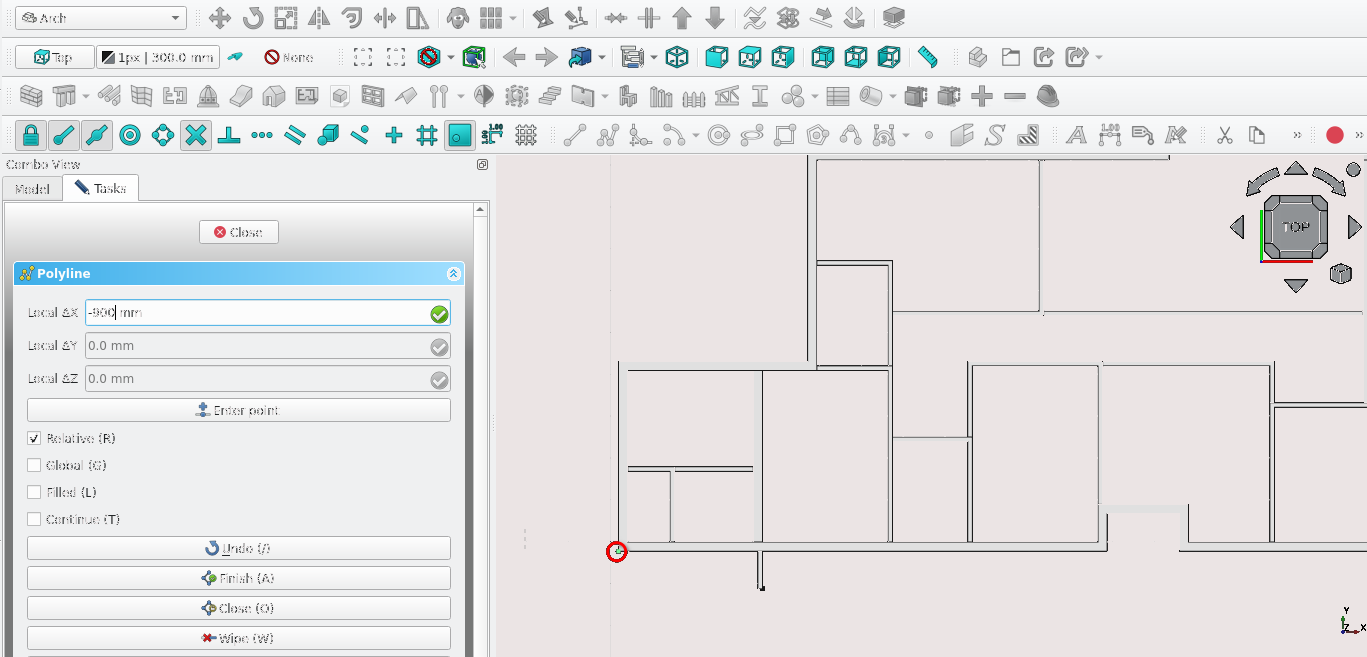
Press 'P' then 'Y' on the keyboard or select the Polyline tool icon (
)Hover the cursor over the point shown in the image above and select it when the End Point snap icon appears (
) and Snap lock (
) (Ensure End Point snap (
) and Snap lock (
) are toggled on)Press the 'X' key to restrict to the x-axes
Navigate to Combo View>Tasks under Polyline type in -900 mm for Local ΔX then select Enter point
Press the 'Y' key to restrict to the y-axis
Navigate to Combo View>Tasks and under Walls type in -900 mm for Local ΔY then select Enter point
Press 'X' to restrict to the x-axis
Navigate to Combo View>Tasks and under Polyline type in -900 mm for Local ΔX then select Enter point
Press 'W' then 'A' on the keyboard or select the Wall tool icon (
)With the newly created wall selected navigate to Combo View>Model, next to the align property select the drop-down menu and then select Left
Go to the Width property and enter 110 mm
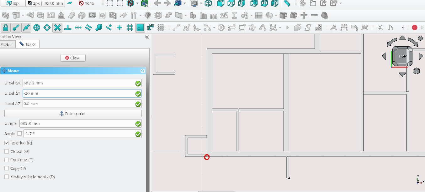
Navigate to Combo View>Model
Press 'M' then 'V' on the keyboard or Select the Move tool icon (
)Hover the cursor over the point shown in the image above and select it when the Point Snap icon appears (
)Navigate to Combo View>Tasks
Under Move type in -20 mm for Local ΔX then type in 682.5 mm for Local ΔY, leave Local ΔZ as 0 mm
Select Enter point or press the 'Enter' key (sometimes more than one press of the 'Enter' key is required) to complete the task
Note: Moving items such as walls or windows does not move their base items (sketches or wires). It is often better to move base items as this will move the item it is linked to
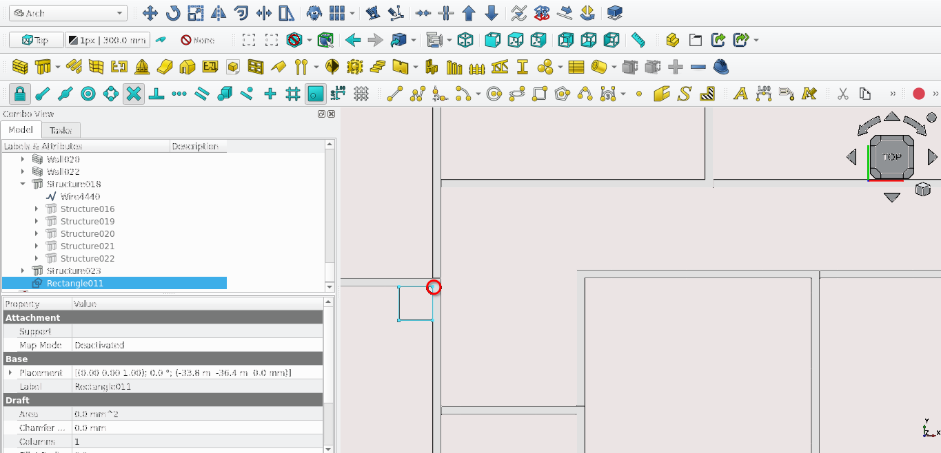
Press 'R' then 'E' on the keyboard or select the Rectangle tool icon (
)Navigate to Combo View>Tasks and go to Rectangle
For Local ΔX type in -450 mm
For Local ΔY type in -450 mm
Navigate to Combo View>Model Select the newly created rectangle and select the Downgrade tool icon (
) or press 'D' then ‘N’Navigate to Combo View>Model and select the wires highlighted in blue while holding 'Ctrl'
Release the 'Ctrl' key and press the 'Delete' key
Navigate to Combo View>Model select the remaining edges while holding 'Ctrl'
Select the Upgrade icon (
) or press 'U' then 'P'
Navigate to Combo View>Model Select the newly created wire then press 'W' then 'A' on the keyboard or select the Wall tool icon (
)With the newly created wall selected navigate to Combo View>Model, next to the align property select the drop-down menu and then select Left
Go to the Width property and enter 110 mm
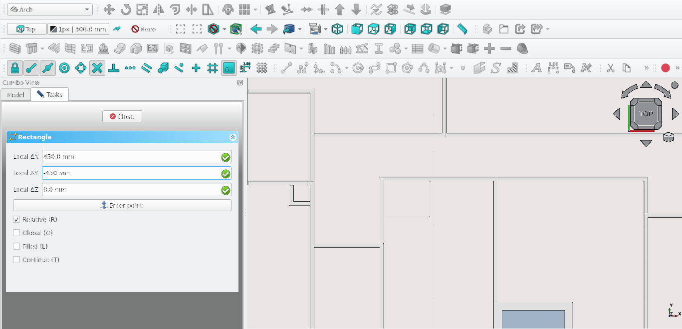
Press 'R' then 'E' on the keyboard or select the Rectangle tool icon (
)Navigate to Combo View>Tasks and go to Rectangle
For Local ΔX type in 450 mm
For Local ΔY type in -450 mm
Navigate to Combo View>Model Select the newly created rectangle and select the Downgrade tool icon (
) or press 'D' then ‘N’Navigate to Combo View>Model and select the wires highlighted in blue while holding 'Ctrl'
Release the 'Ctrl' key and press the 'Delete' key
Navigate to Combo View>Model and select the remaining edges while holding 'Ctrl'
Select the Upgrade icon (
) or press 'U' then 'P'
Navigate to Combo View>Model Select the newly created wire then press 'W' then 'A' on the keyboard or select the Wall tool icon (
)With the newly created wall selected navigate to Combo View>Model, next to the align property then select the drop-down menu then select Left
Go to the Width property and enter 110 mm
Part 8: Creating Slabs
Setting up Snap Points
Toggle on the following snaps by selecting their icons; Snap lock(), Snap Endpoint (
), Snap Midpoint (
), Snap Working Plane (
) and Snap Grid (
)Press 2 on the keyboard to go to the top view or select the top view on the cube
Creating the main slab
Press 'P' then 'Y' on the keyboard and trace the Exterior walls
Select the newly created wire and press 'O' then 'S' or select the Offset tool icon (
)Move the cursor outside of the building
For the distance value enter 900 mm and press 'Enter'
Navigate to Combo View>Data select both Wires and set the Make face property to true
Select the larger Wire then the small one while holding 'Ctrl', then release 'Ctrl'
Select the Small structure then the larger structure while holding 'Ctrl', then release 'Ctrl'
Select the Arch remove tool(
)
Creating a base For the slab
Press 'R' then 'E' or select the Rectangle tool icon (
)Select the point highlighted in the image above
Select the opposite corner highlighted in blue
Press 'Enter' on the keyboard
Select the newly create rectangle and select the Structure tool (
)Select the newly created structure and press 'M' then 'V'
Navigate to Combo View>Task>Move
Press 'Z' To Restrict to the Z axes
For Local ΔZ enter 200 mm and select Enter point
For Local ΔZ enter 200 mm and select Enter point
Combining slab objects
Select the small structure then the large one while holding 'Ctrl'
Select the point highlighted in the image above
Then select the Add component tool icon (
)
Cutting the slab
Press 'R' then 'E' on the keyboard or select the Rectangle tool icon (
)Trace the wall using Snap endpoint snap
Navigate to Combo View>Model
Select the newly created rectangle and then select the Structure tool (
)Navigate to Combo View>Model; While holding 'Ctrl', select the newly created Structure then the old structure and select the Remove component tool icon (
)
Creating a base for the shower slab
 s
s
Press 'R' then 'E' or select the rectangle tool(
)Trace the wall using Snap Endpoint and the Polyline tool
Navigate to Combo View>Model
Select the rectangle and select the Structure tool (
)Navigate to Combo View>Model. While holding 'Ctrl' select select the newly created Structure then the old structure and select the remove component icon (
)
Creating a base for the ramp slab
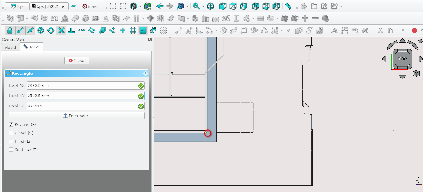
Press 'R' then 'E' or select the Rectangle tool icon (
)Navigate to Combo View>Tasks
For Local ΔX type 2880 mm
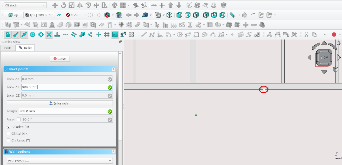
For local Local ΔY enter 2500 mm
Navigate to Combo View>Model and select the newly created rectangle
Press 'M' then 'V' on the keyboard or Select the Move tool icon (
)Press 'Y'
For Local ΔY enter 500 mm
Select the newly create rectangle and select the Structure tool (
)Select the newly created structure then the Larger structure and select the remove component icon (
)
Creating a base for the ramp slab
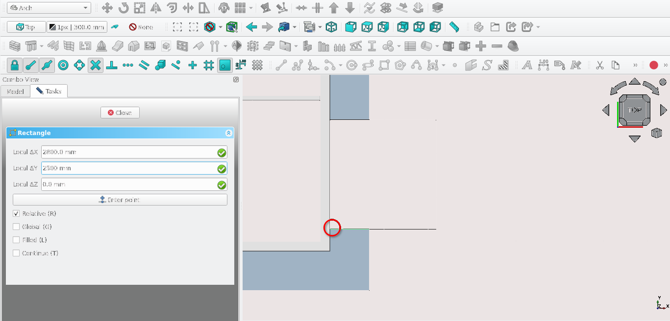
Press 'R' then 'E' or select the Rectangle tool icon (
)Select the point highlighted in the image above
For Local ΔX type in 2880 mm
For Local ΔY enter 2500 mm
Press 'Enter' on the keyboard
Press 'V' Then 3
Creating a slab to cut the ramp
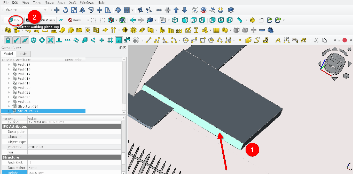
Select the face of the newly created structure shown above and then the active plane icon (It will change from Top to Custom)
Press '3' on the keyboard or orbit so that you can view the Front side of the structure
Select the face of the newly created structure in view
Press 'L' then 'I' or select the Line tool icon
Select the vertexes of the structure shown above to create a line
Using the Cut with line tool to cut the ramp
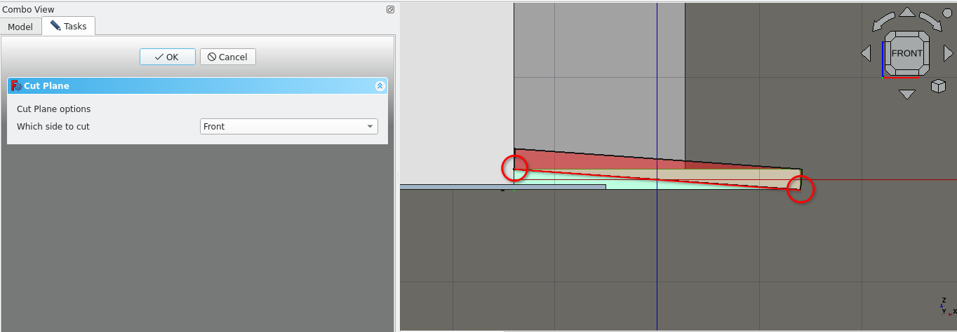
While holding 'Ctrl' select the desired object to be cut in Combo View>Model then select the newly created line
Release the 'Ctrl' key on the keyboard key and select the cut with line tool icon
Under Combo View>Tasks select front for which side to cut
Select 'Ok'
This cuts the structure and places a cut object as a sub-object of the structure object. If deleted this would restore the structure to its original shape
Creating a slab to cut the ramp
Press 'V' then 3
Press 'P' then 'Y' or select the Polyline tool
Trace the shape shown in red shown above (make sure the active plane is set to top and Snap to plane is toggled on)
Select the newly created polygon
Select the Structure tool (
)Select the newly created structure then the larger structure and select the Remove component icon (
)
Creating a slab for the verandah
Press 'V' then 3 on the keyboard
Press 'P' then 'Y' on the keyboard or select the Polyline tool icon
Trace the shape shown in red
Select the structure icon (
)Press 'V' then 1
Filling in a gap with the Structure tool
Filling in a gap with the Structure tool
Press 'V' then 3 on the keyboard
Press 'P' then 'Y' on the keyboard or select the Polyline tool icon
Trace the shape shown in red (in the image above)
Select the structure icon (
)Press 'V' then 1
Joining Slabs
Select the Structure Labelled 1 then 2 while holding 'Ctrl' as shown in the image above
Release 'Ctrl' and select the Add component icon (
)With the structure still selected option click and select add dependent objects to selection
Navigate to Combo View>Model>Structure and set the height property to 50 mm
Creating the porch slab
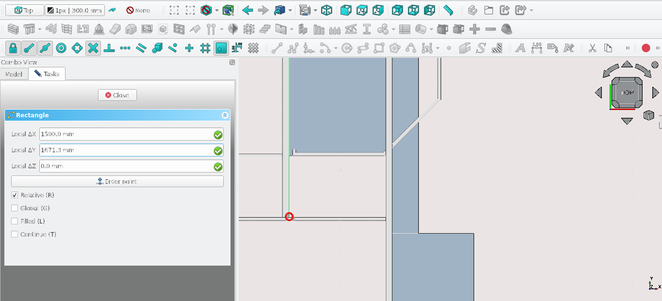
Press 'R' then 'E' on the keyboard or select the Rectangle tool icon (
)Select the point shown above
For Local ΔX enter 1500 mm
For local Local ΔY enter 1671.3 mm
Press 'M' then 'V' and select the newly created rectangle
Select the newly created Rectangle at the same point
For ‘Local ΔY’ enter 220 mm
Press ‘Enter’ or select ‘Enter point’
Select the Structure icon (while the rectangle is still selected)
Navigate to Combo View>Data>Structure and set the Height property to 150 mm
Creating the porch slab part 2
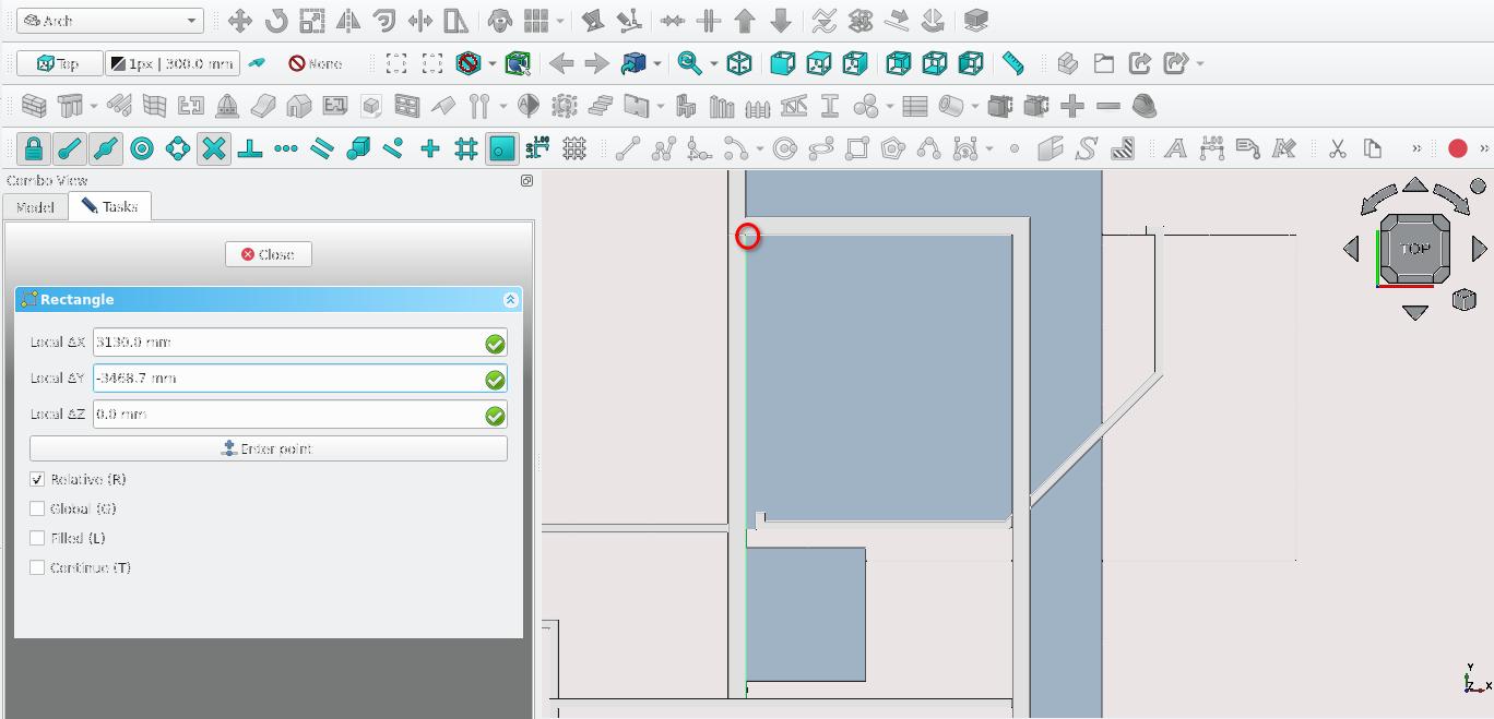
Press 'R' then 'E' on the keyboard or select the Rectangle tool icon (
)Select the point shown above
For Local ΔX enter 3130 mm
For Local ΔY enter -3468.7 mm
Select the Structure icon (while the rectangle is still selected)
Navigate to Combo View>Data>structures and change the Height property to 50 mm
If the structure is extruded in the wrong direction: select the newly created Structure and navigate to Combo View>Data
Under Structure select the arrow next to the Normal property normal and set the Z property to 1
Modifying the porch slab part 2
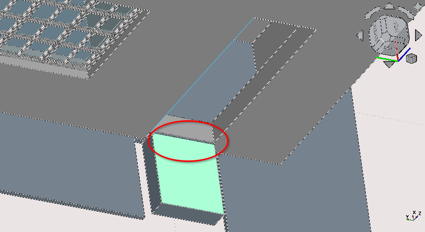
Crop image
Fill in this gap shown above using the Structure tool
Adjust the slab and wall surrounding it to be flush
Add this as a component to the slab labelled ‘WC/Shower 1 Slab’
Set the Height property of ‘Shower Wall Exterior’ to 2100 mm
Creating slabs for each room
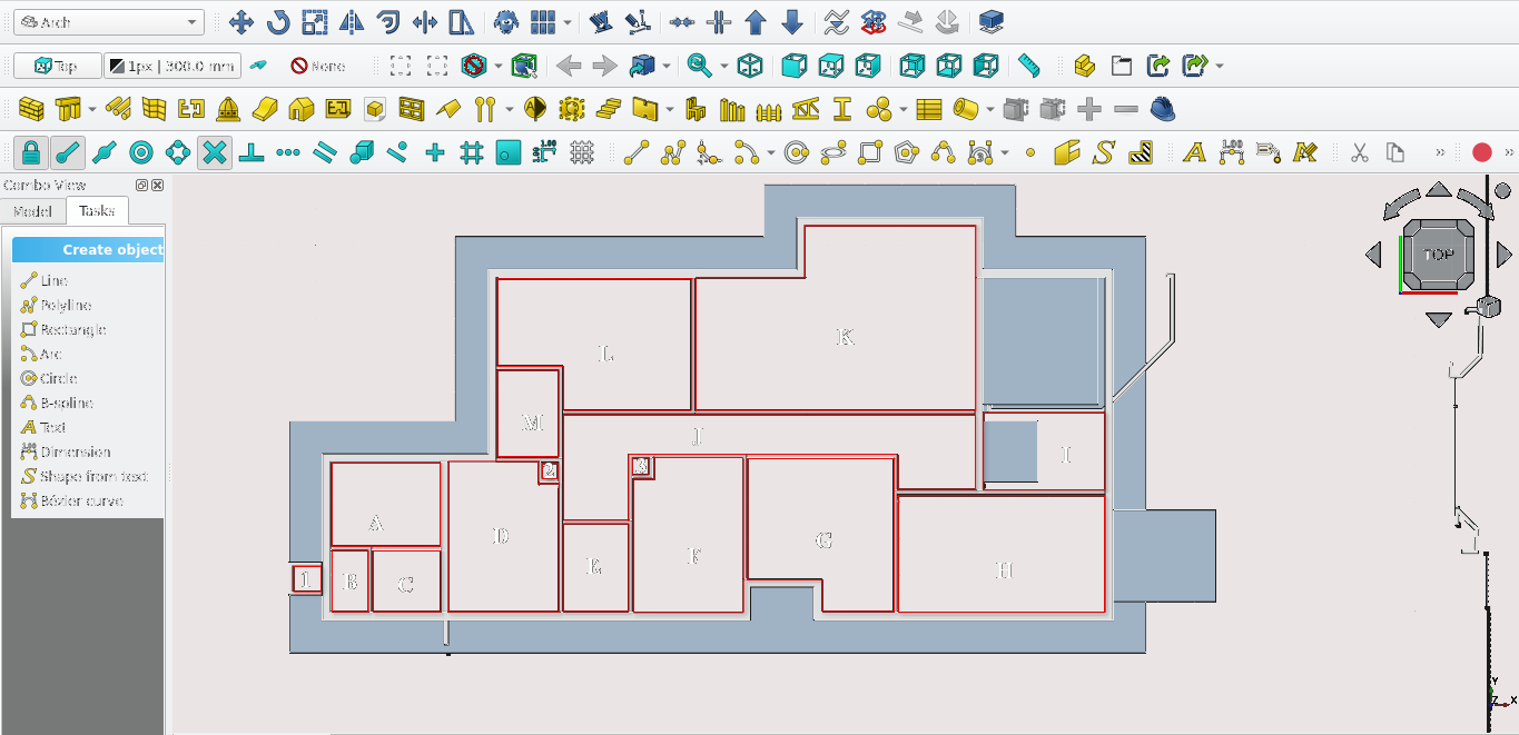
Create polylines for each area indicated above (2D)
Then while the 2D object is selected in Combo View>Model, select the Structure icon (
)
If necessary navigate to Combo View>Model to make adjustments
If necessary further modify said object using cut plane, remove component or add component
Set the Height property of every (floor slab) except H to be 150 mm (H should have a height of 200 mm)
Do not create a slab for room I (are you paying attention?)
Part 9: creating openings
Facade or right view openings
Press '3' on the keyboard
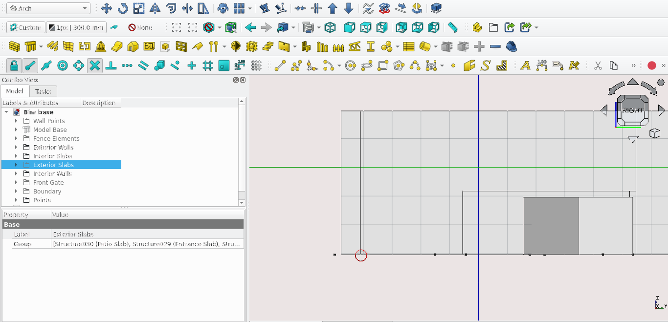
Select the Face shown Above and select the Active Plane icon (
), this constrains Drawing to the plane selected
Press 'V' then 3
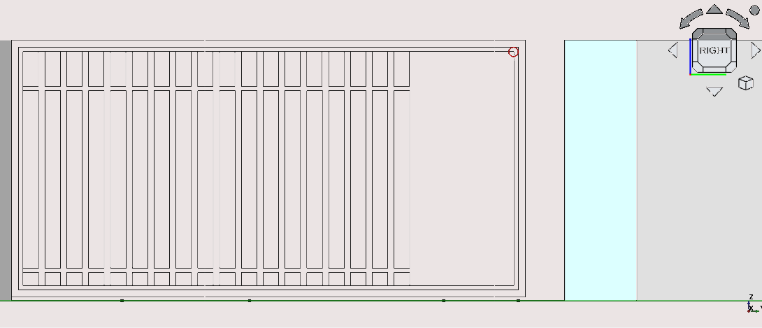
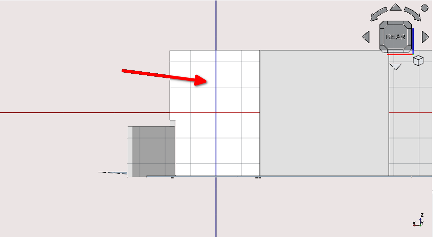
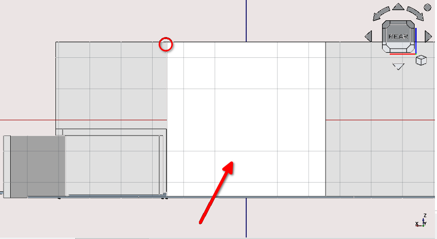
Create a rectangle (
) Start the rectangle at the point circled aboveThe rectangle should have a height of 2215 mm and a length of 6020 mm
With the newly created Rectangle selected, select the Window tool icon (
) or press 'W' then 'N'With the newly created Rectangle selected navigate to Combo View>Data>Window and change the following properties
For Hole Depth: enter 220 mm and for the Host property select the Field. This opens the link menu
Adding components to a wall
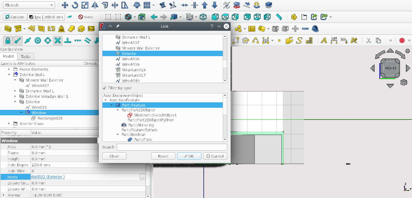
The Filter By Type option will allow you to more easily find items
Select the option Class ArchWall._Wall to search for items that are walls
Doing this places the Window item and their base as a sub-component of the wall
Hide the window item (this leaves a gap in the wall)
Rename the window as ‘Verandah Entrance 1’
Create a rectangle (
) starting at the point highlighted aboveThe rectangle should have a height of 2015 mm and a length of 2500 mm
Select the newly created rectangle and press ‘M’ then ‘V’ or select the Move tool icon. Select the same point indicated above
For Local ΔX and type in 500 mm
For ‘Local ΔY’ enter 200 mm
Select the rectangle and press ‘O’ then ‘S’ or select the Offset icon (
)Ensure sure both rectangles have the Make face option set to true, this option can be found under Combo View>Model Blocks
The offset distance should be 20 mm (move the mouse with the rectangle selected and place it inside the newly created rectangle)
Select both Rectangles (select the larger one first and remember to multi-select objects; you can hold 'Ctrl' while selecting with the mouse) then select Draft2Sketch icon (
)Delete the two Rectangles
Select the newly created sketch press ‘W’ then ‘N’ or select the Window icon (
)
Select the newly created rectangle and press ‘W’ then ‘N’ or select the Window icon (
)
With the newly created Window selected Navigate to Combo View>Data>Window and change the following properties
For Hole Depth: enter 220 mm and for the Host property select the Field icons ‘…’
Select the wall labelled ‘Exterior’ in the link menu popup
Hide the Window and rename it as ‘Garage entrance’
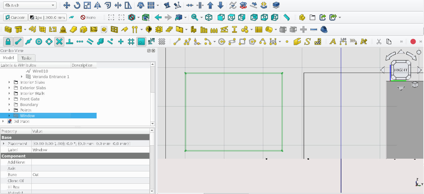
Select the ‘Garage Entrance’
This opens the window elements in Combo View>Tasks
Under Components select the item listed Default then select edit
Creating The Garage Door Frame
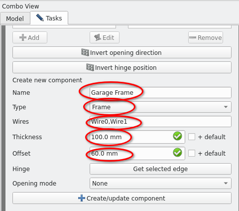
Change the Name Field to: ‘Garage Frame’
Change the Type field to Frame
Set the Thickness field to 100 mm
Set the Offset field to 60 mm
Select the Wire Field then scroll up and select the two wires under ‘Wires’
Select Create/update component
Creating The garage door
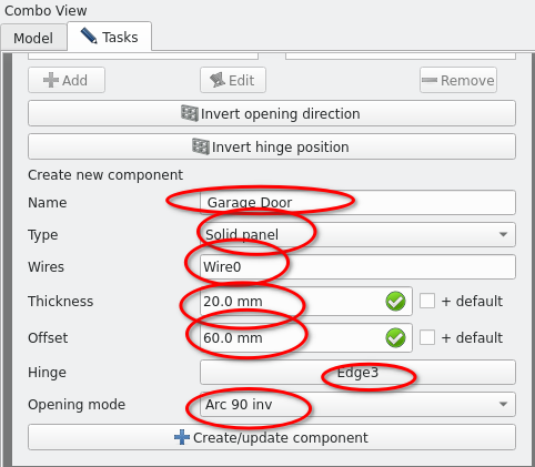
Select the item labelled ‘Default’ and select ‘Edit’
For the name field enter ‘Garage Door’
For the Type field enter Solid Panel
Select the ‘Wire’ field then scroll up and select Wire0 under ‘Wires’
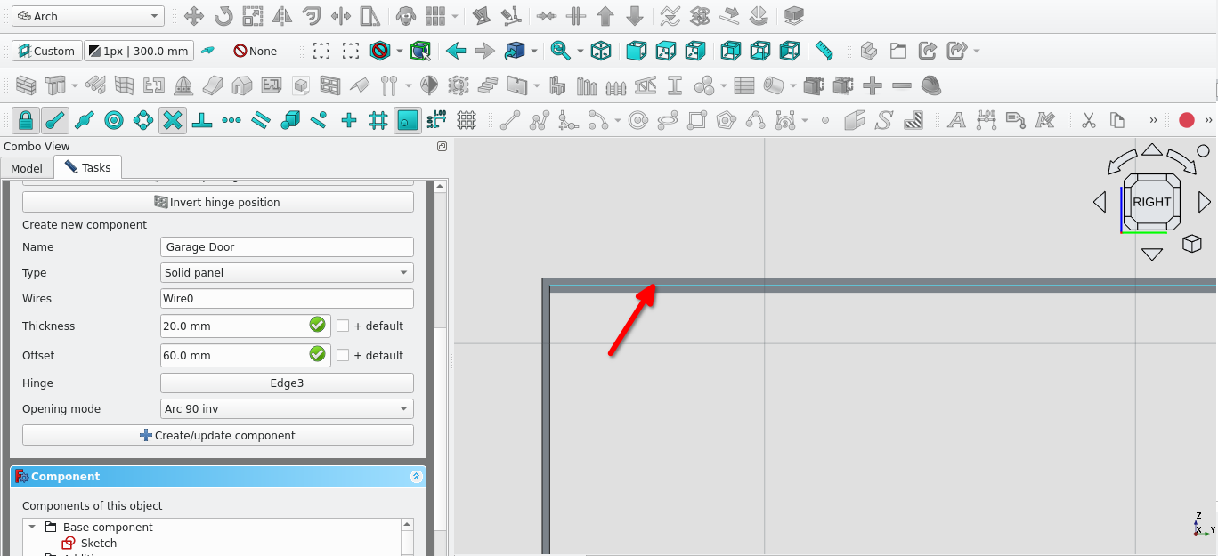
For the Hinge field select the Edge shown above then Navigate back to Combo View>Tasks>Window and select ‘get selected edge’ in the Hinge field
For the Opening mode field select ‘Arc 90 Inv’
Select Create/update component
Under components delete the default item then select close
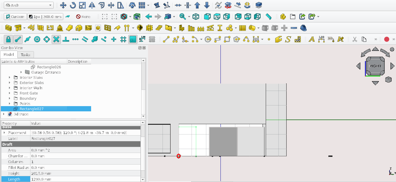
Create a rectangle starting at the point circled above it should have a height of 2015 mm and a length of 1200 mm
Select the Rectangle and press the Downgrade icon (
)
Select the top most edge and offset it by 35 mm
Select the Bottom most edge and offset it by 35 mm
Select the left most edge and move it by 30 mm (press ‘P’ to use the copy option)
Select the Right most edge and move it by -30 mm (press ‘P’ to use the copy option)
Creating front door
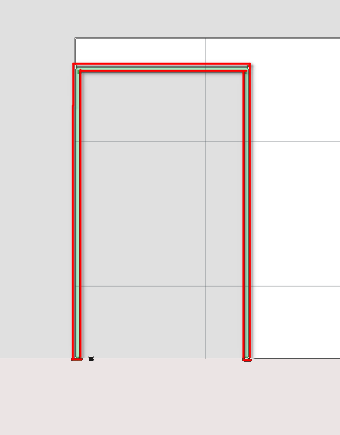
Use the trim tool to create a the wire shown above
Close the frame using two lines
Use the Upgrade tool(
 ) to join the lines
The wire selected select the Draft2sketch tool(
)
With the sketch selected press the window tool
Rename the window as ‘Main Door Frame’
Navigate to Combo View>Model and double-select ‘Main Door Frame’
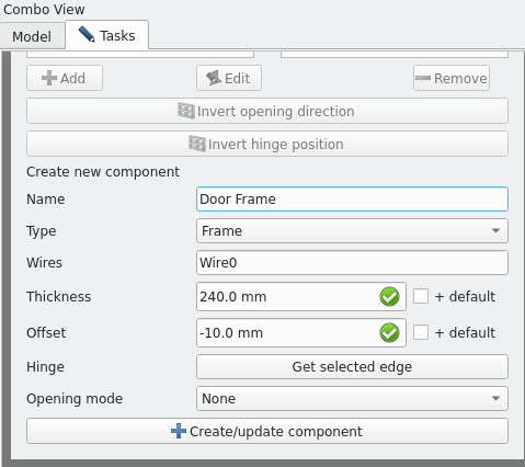
Input the details shown above
Select create/update component
Navigate to Combo View>Tasks>window elements under components. Delete the item labelled default
Select close
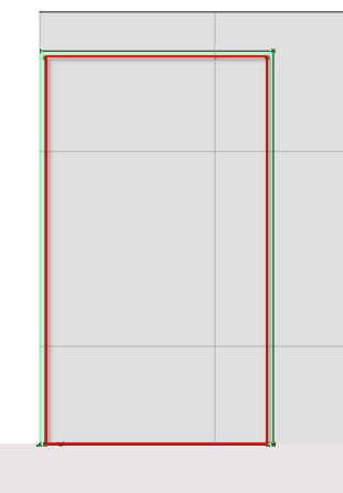
Create a rectangle that traces the inner part of the frame as shown above
With the rectangle selected press the draft2sketch icon (
)
With the sketch selected selected the Window icon ()
Rename the window as ‘Front Door’
Navigate to Combo View>Tasks>Window
Input the details shown above
Select create/update component
Navigate to Combo View>Tasks>Window elements under components delete the item labelled default
Select close
Placing the Front Door
Change the view to wireframe (as view setup described some distance above)
Select both sketches of the ‘Front Door’ and the ‘Frame front’ Door’
Move the sketches by selecting the bottom left corner (moving the sketches moves the object linked to them)
For Local ‘ΔX’ enter -455.6 mm
For ‘Local ΔY’ 200 mm
Step 14: Creating Openings (Rear Side)
Setup
Turn on Snap lock (
) and the following ; Snap Endpoint ( ), Snap Midpoint (
), Snap Working Plane (
), Snap Grid (
)
), Snap Midpoint (
), Snap Working Plane (
), Snap Grid (
)
Navigate to Combo View>Model
Hide the ‘Front Gate’ Group, ‘Exterior Slabs’ Group and the ‘Boundary’ Group
Press 4
Select the face of the wall shown above and set it to the active plane
Creating An Opening For The Verandah
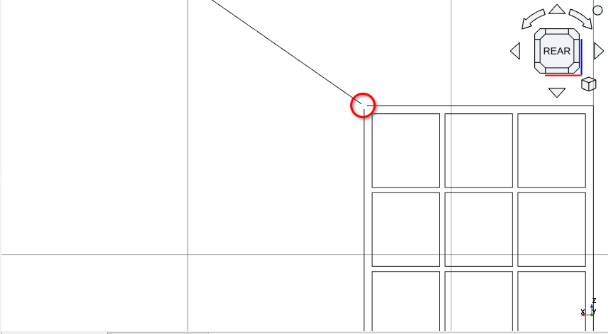
Create a rectangle starting from the left-most point indicated above
Select the first point then second point indicated above
Use the rectangle to create a window
Change the Hole depth of the window to 220 mm and window host object to ‘Exterior’
Rename it to Verandah entrance 2 (you can do so by selecting the object in Combo View>Models and pressing F2)
Select the Face shown above and make it the active drawing plane
Create a rectangle starting from the point circled above; it should have a height of 1540 mm and a length of 870 mm
Select the rectangle and offset it inwards by 30 mm
Create a rectangle of height 280 mm and length 276.7
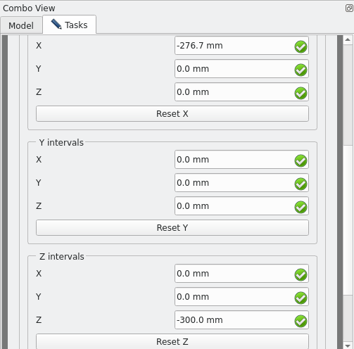
Select the rectangle and create an array using the following settings
Number of X should be 3
Number of Y should be 1
Number of Z should be 5
Set the interval Fields as shown above
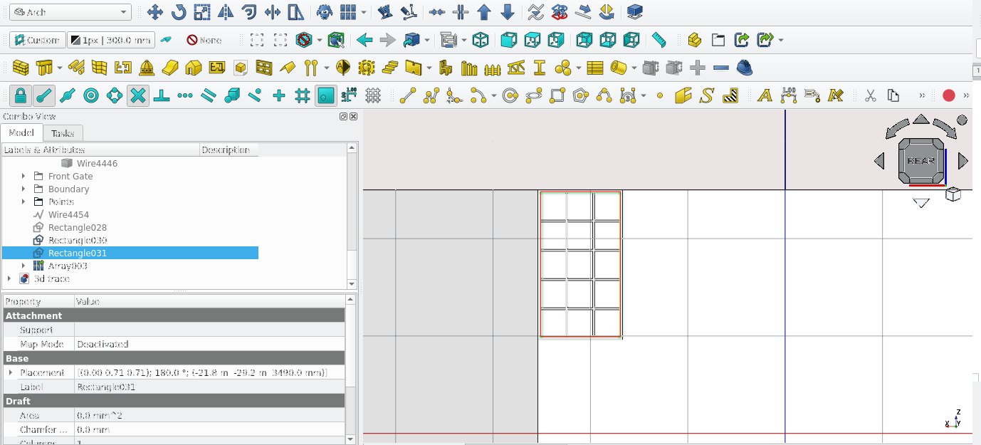
Select the rectangle shown above and delete it
Move the sketch; use the point indicated above as a starting point. It should be moved 4209.9 mm in the X direction and -29350 mm in the Y direction
While the sketch is selected, select the Window icon (
)
Rename the window as ‘w10‘
Double-select w10 in Combo View>Model
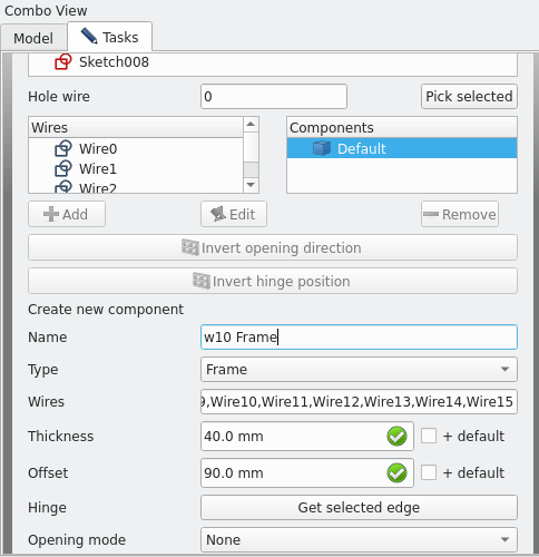
Modify the fields as shown above
Select create/update component
Under Combo View>Tasks>Window elements
Delete the component labelled default
Select add component
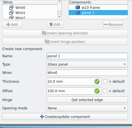
Enter the details shown above and select create/update component
Number each panel you create
The process of the window tool extrudes and offsets the sketch that it is tied to.
As such repeat this process to add glass to each part of the frame
When complete move the window 130 mm to the left (select the sketch not the window)
Be sure to set the type to Glass panel
Using the clone tool
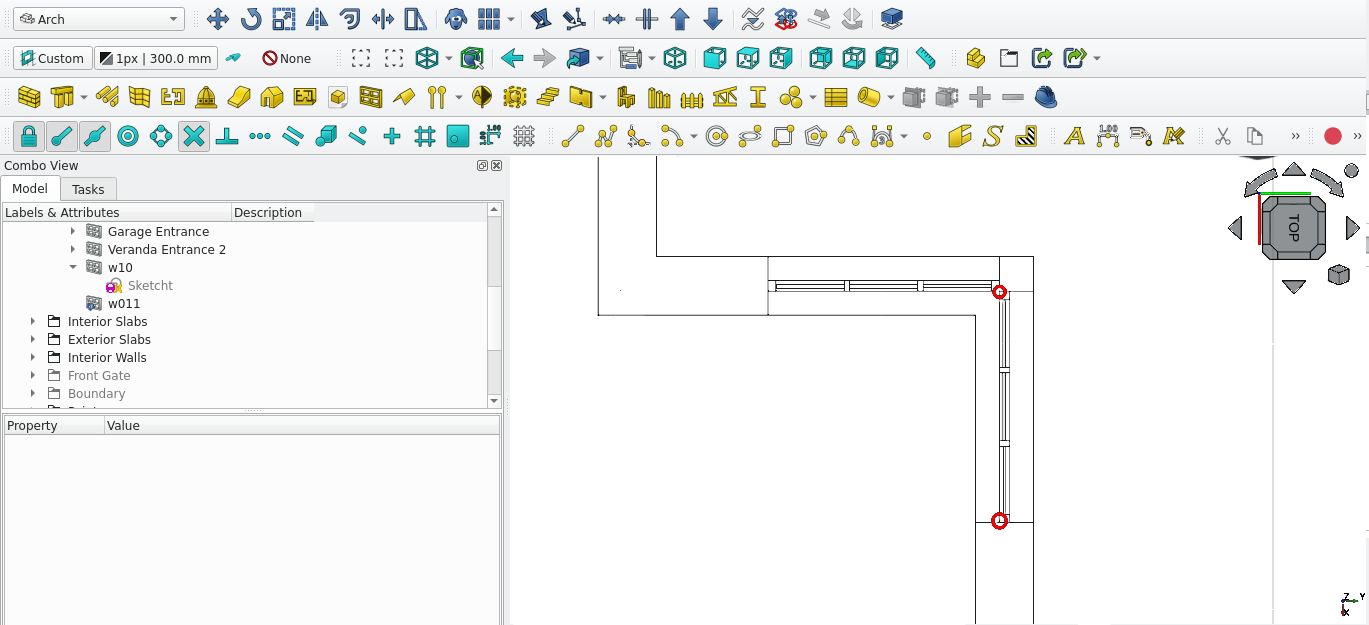
Change to ‘Top View’ and set the draw style to Wireframe (‘V’ then ‘3’) or View>Draw style>Wireframe
When complete make a clone of the window by selecting it and pressing the Clone icon (
) (rotate ‘w011’ by 90 degrees)
Use the move tool to place the window as shown above (the clone of the window should be centre of the wall)
Remember to turn off Snap working plane and set the Working plane to Top or it will rotate about a different axis than the one that is required
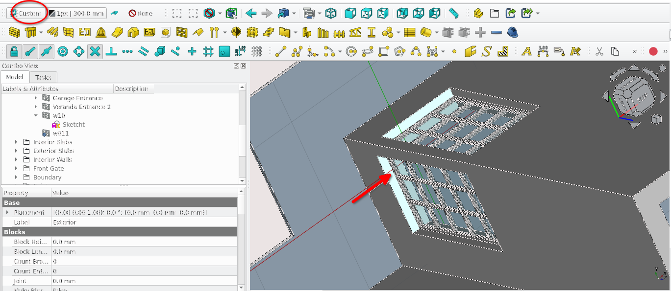
Change to ‘Top View’ and set the Draw style to Wireframe
The benefit of cloned items is that a change to the original will alter child clones automatically
Set the cloned windows properties under Combo View>Data>Window
For hole depth to 220 mm and hosts to the the ‘Exterior’ wall
Using the remove tool to cut walls
Turn on Snap lock (
) and the following; Snap Endpoint (
), Snap Midpoint (
), Snap Working Plane (
), Snap Grid (
)Navigate to Combo View>Model
Set the active working plane to the plane shown above
Set the view Drawing style to Wireframe
Select the face of the wall shown above and set it to the active plane
Set the view to Top (press 1)
Create a rectangle () as shown above
With the Rectangle selected, navigate to Combo View>Data and change its Make face property to true
With the rectangle created, select the Wall tool icon (
)
Select the newly created wall and navigate to Combo> View>Data>Wall
Set its height property to 1540 mm
Navigate to Combo View>Model and while holding ‘'Ctrl' select ‘Wall’ and then Exterior Wall then select the Remove component icon (
)
Creating support for the windows
Create a square of 40 by 40 mm
Create a structure from the square
Rename The structure as ‘W10 Support’
Navigate to Combo View>Data while ‘W10 Support’ is selected
set its height property to 1540 mm
Press 4
select the face shown above and make it the active plane
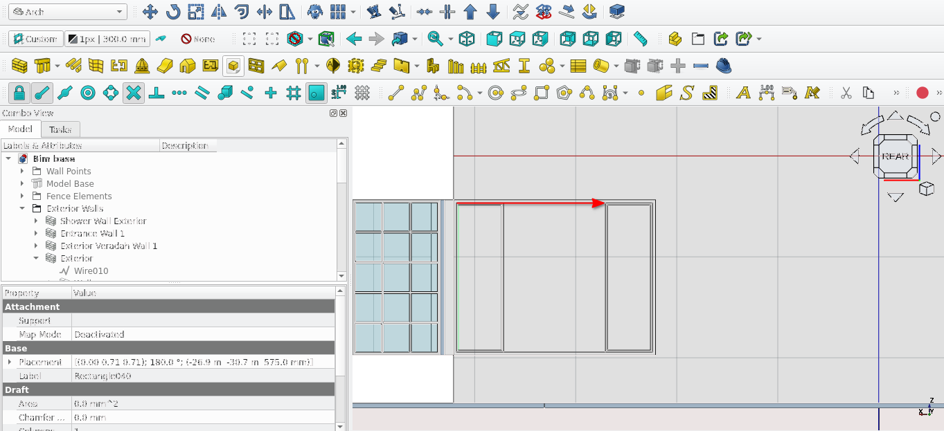
Create a rectangle starting with the point shown above (The rectangle should have a height of 1540 mm and a length of 2000 mm)
Offset the rectangle by 30 mm inwards
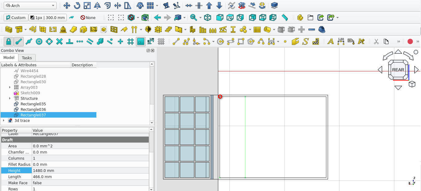
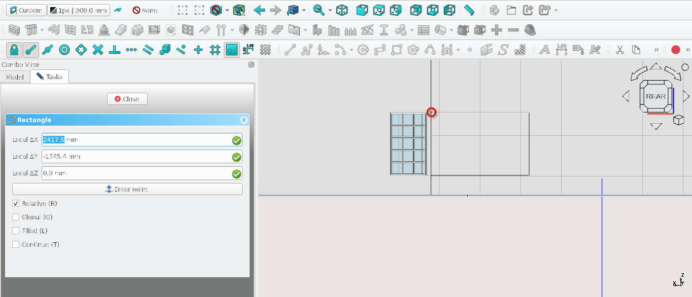
Create a rectangle of height 466 mm and length 1480 within the previously created rectangle
Move the rectangle by 1474 mm
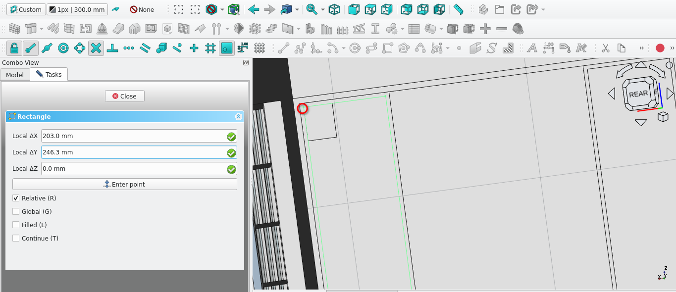
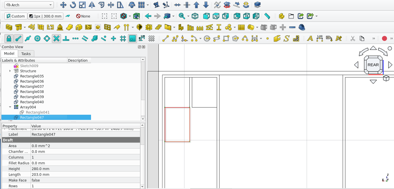
Create a rectangle of height 236.3 and a length of 203 at the point indicated above
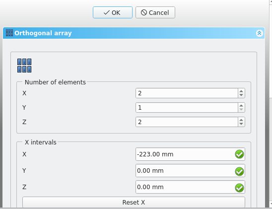
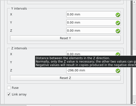
Create an array of the rectangle using for Number in ‘X’ enter 2 for the x interval (leave the other interval values at 1) enter-223 for the X field enter 0 mm, for the y field enter 0 mm and lastly enter 0 mm for the Z field (leave all other interval fields at 0 mm
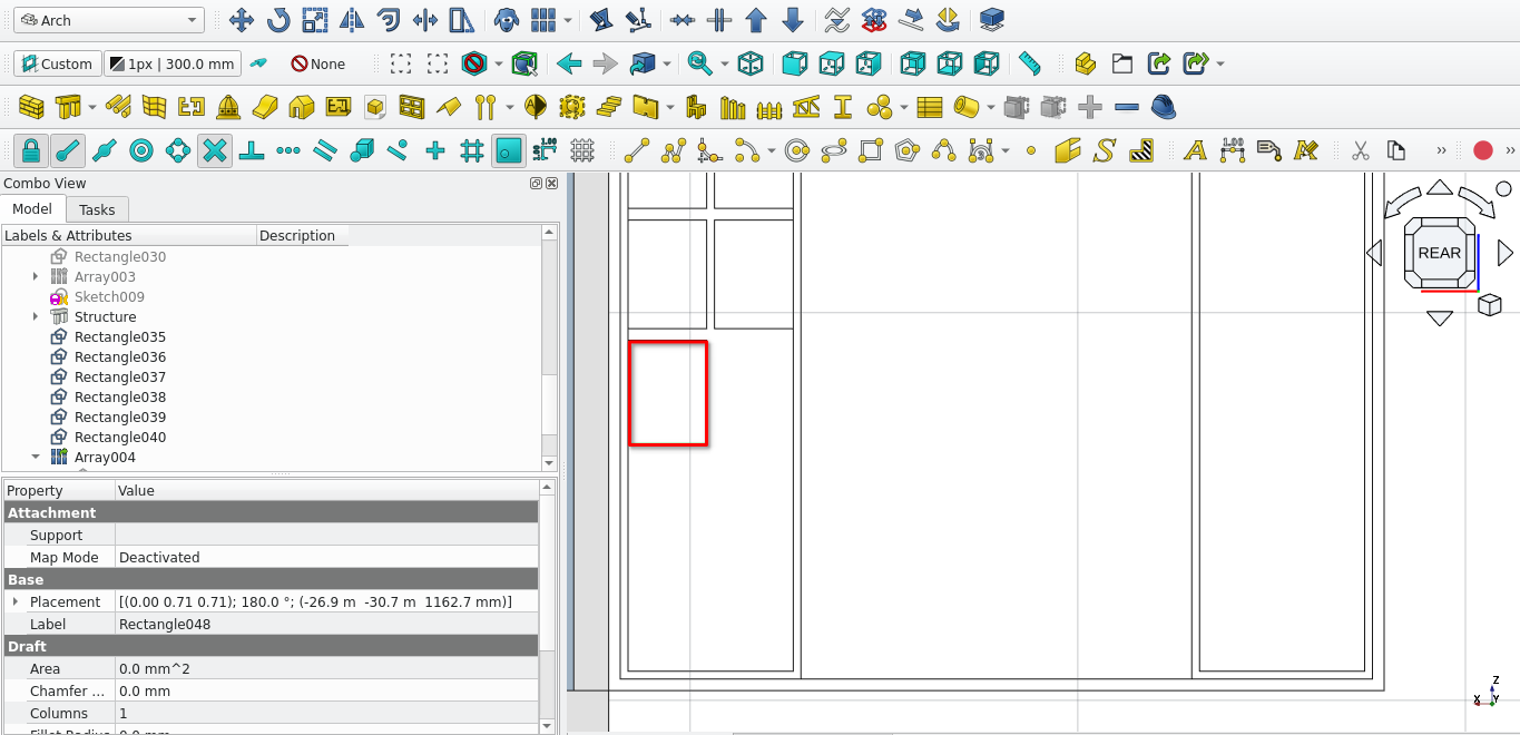
Create a rectangle below the previously created one (it should have a height of 280 mm and a width of 203 mm)
Move the rectangle by 30 mm in the y direction (away from the rectangle above it)
Create a copy and move the rectangle 223 mm in the x direction (away from the original / use the array tool)
Create a rectangle of width 203 mm and height 266 mm
Move the rectangle 30 mm in the y direction (away from the original position)
Create an array of the rectangle with the settings shown in the image above
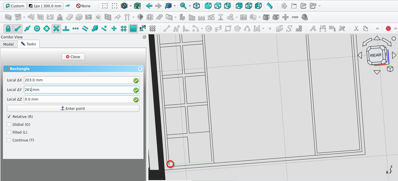
Create a rectangle at the point indicated above it should have a width if 203 mm and a height of 261.7 mm.
Copy and move the rectangle 223 mm in the x direction from the point indicated in the image above
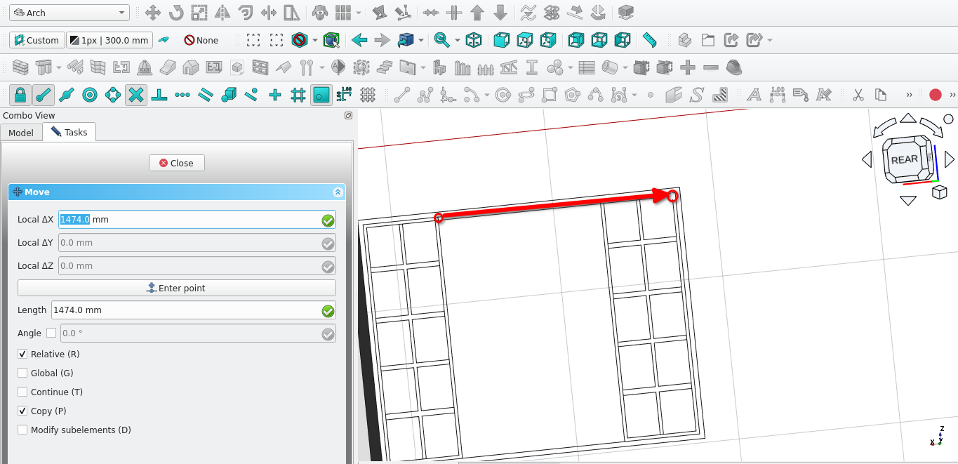
Copy the rectangles and their array and move them 1474 mm as per the image above
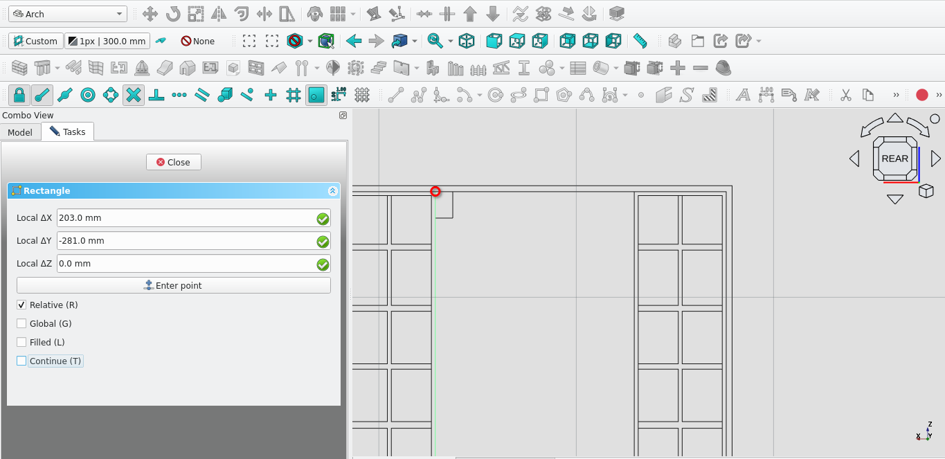
Create a rectangle(
) of width of 223 mm and a height of 281 mmSelect the created rectangle and make an array
Navigate to Combo View>Tasks>orthogonal Array
Under number of elements; the x field should be 4, the y field should be 1, and the z field should be 1.
For X intervals enter -243 mm for the x field and leave all other fields as 0 mm)
Move the array by 28 mm in the x direction
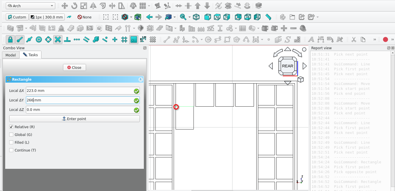
Create a rectangle at the point indicated above the rectangle should have a width of 223 mm and a height of 266 mm
Create an array (
) of the previously created rectangle
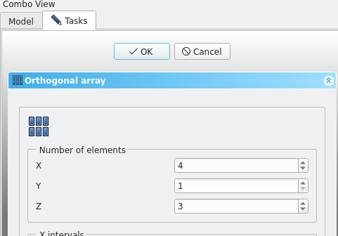
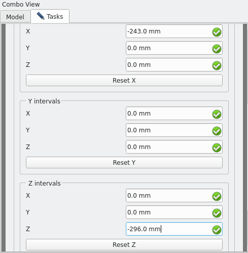
Use the above settings to create the array
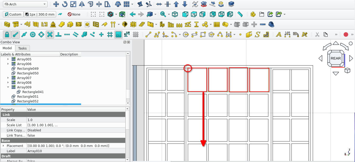
Select the array highlighted above and move it using the point indicated above by -1199 mm in the y direction
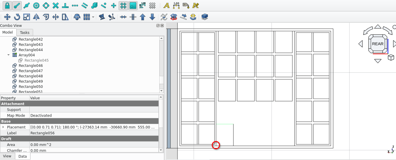
Create a rectangle starting at the point indicated above it should have a height of 281 mm and a width of 223
Move the rectangle 28 mm to the right in the x direction
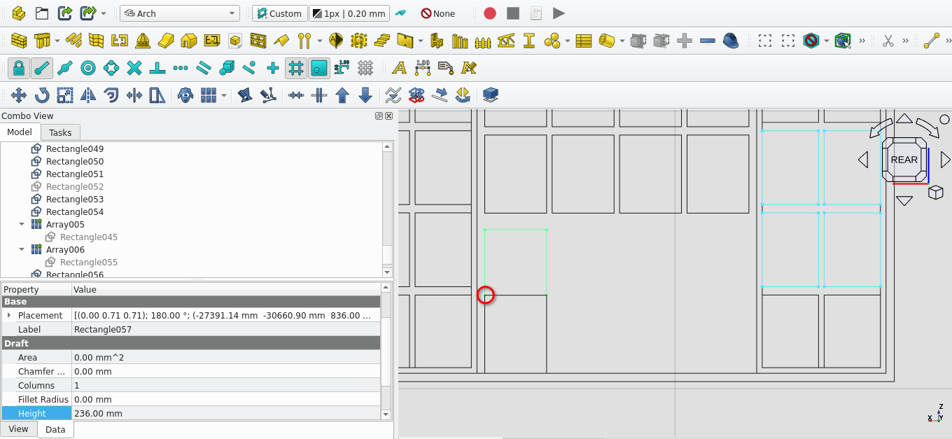
Create a rectangle at the point indicated above. The rectangle should have a length of 223 mm and a height of 236 mm
once created move the rectangle upwards (in the y direction) mvby 30 mm
create arrays of the two recently created rectangles
For the Number of elements enter 4 in the x field and 1 in the Z and Y fields the spacing should be 243 mm
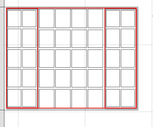
Delete the wires highlighted above
Select the remaining wires and and select the draft2sketch icon (
)
Delete the wires used to create the sketch
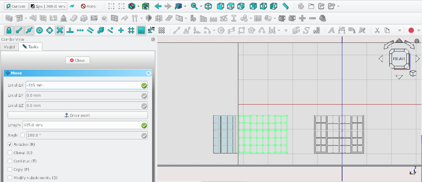
Move the sketch 335 mm in the x direction
Double-select the sketch and check for overlapping lines and delete them as they will cause issues with the window tool. Press ‘'Esc'’to stop editing the sketch
Select the moved sketch and make a window
Creating The Main Frame of w9
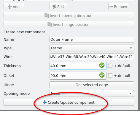
Select the add icon (
) in Combo View>Tasks>Window elements
Use the above settings to create the inner frame of w9 select the appropriate wires
For the wire field
Creating The Inner Frame W9
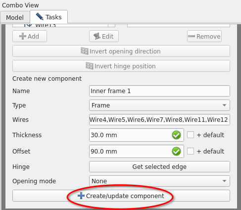
Set the properties as shown in the image above and repeat this process to create the second inner frame
Creating window panels W9
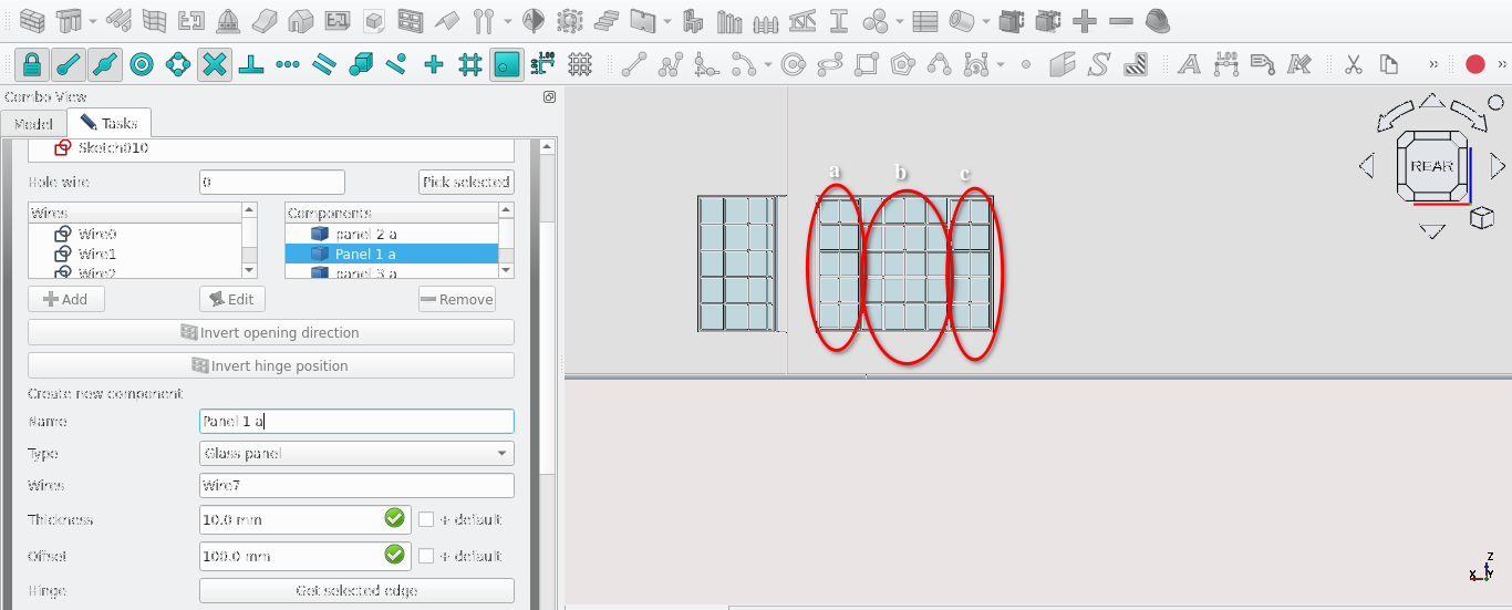
Select the add icon in Combo View>Tasks>Window elements
Use A thickness of 10 mm for the glass panel
And an offset of 100 mm
Name each glass panel methodically so that it is easy to edit or refer back to them
Label each panel with a letter and each panel with a number going from left to right
Cloning and moving W9
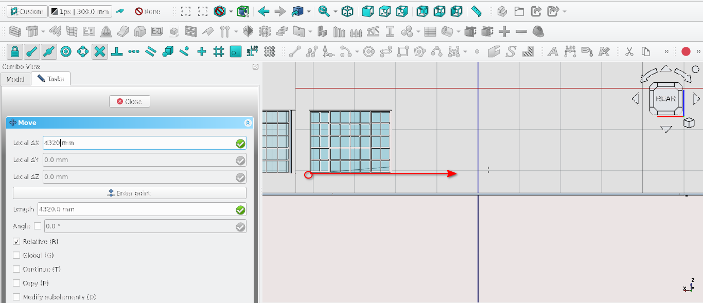
Create a clone() of W9
Move (
 ) the clone 4320 mm in the x direction (relative to active
plane)
) the clone 4320 mm in the x direction (relative to active
plane)
Navigate to Combo View>Data>Base and change the label property to W8
Navigate to Combo View>Data>Window and change the hole depth property to 220 and the set the ‘Host’ to the wall labelled ‘Exterior’
Get icon
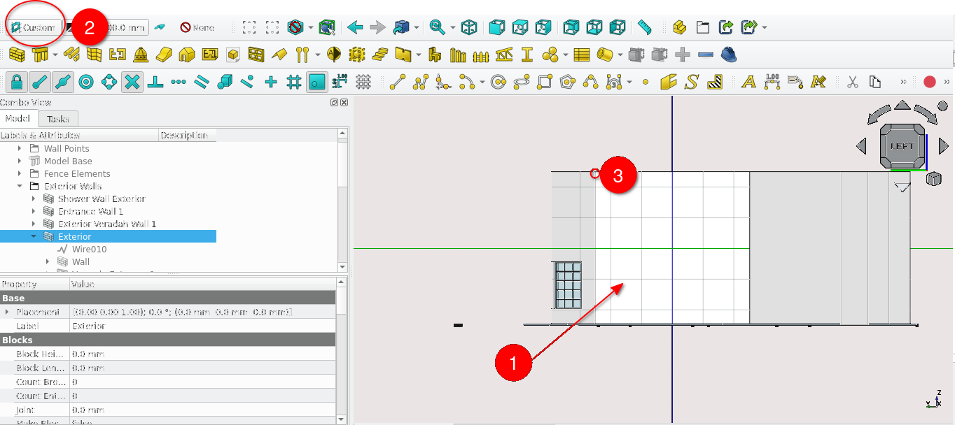
Press ‘6’ to got to the left view (the rear of the house)
Select the face shown above and make it the active working
Create a rectangle at the point indicated above it should have a width of 1022 mm and a height of 939 mm
Offset the rectangle by 30 mm inwards
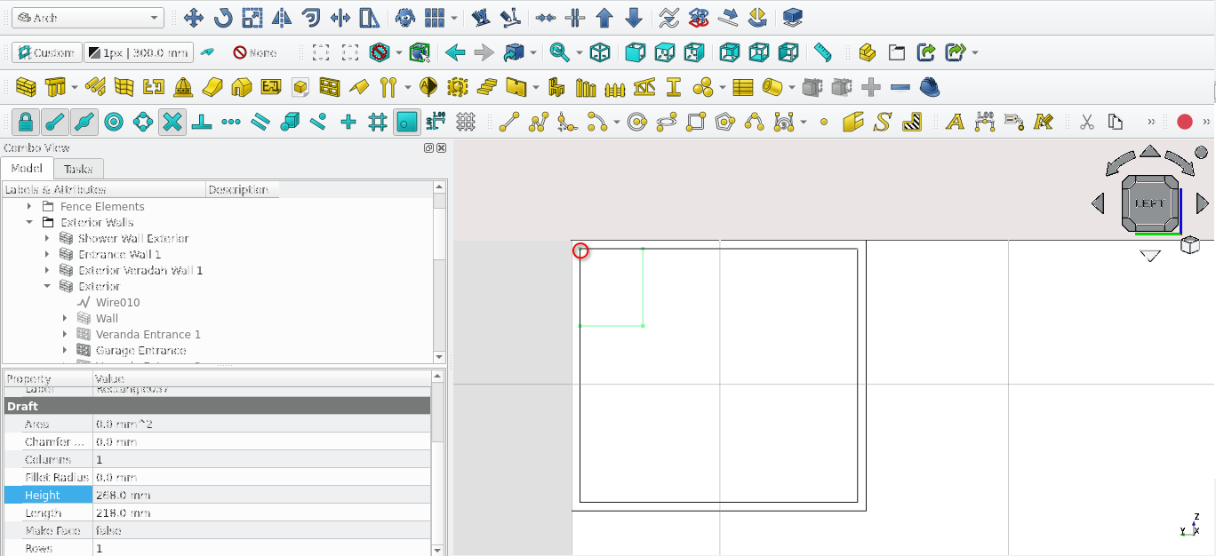
Create a rectangle at the point indicated above it should have a length of 218 and a height of 268 mm
Copy and move the rectangle such that there is a 20 mm gap between the copy and the original
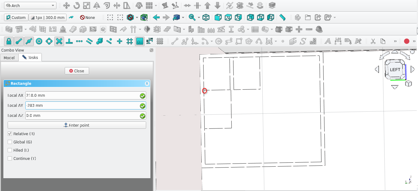
Create a rectangle at the point indicated above the length of which should be 218 and the height of which should be 283 mm
create a 30 mm gap between the (218 mm by 283 mm and the 218 mm by 268 mm rectangle
Create a copy of the 218 mm by 283 mm rectangle and move it such that there is a 30 mm gap between it and its original
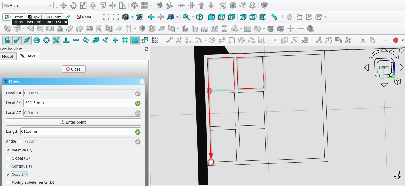
Move and make copies of the highlighted rectangles; they should be moved and copied by -611.6 mm
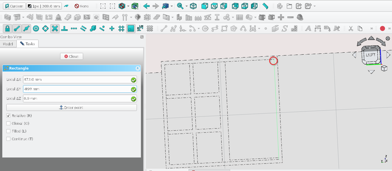
Create a rectangle starting from the point indicated above; it should have a width of 473 mm and a height of 899 mm
Offset this rectangle by 20 mm (inwards)
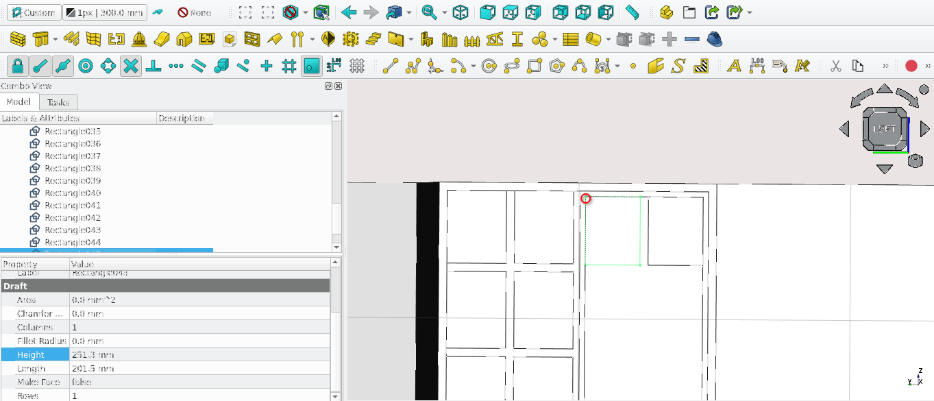
Create a rectangle that is 201.5 mm in width and 251.3 mm in height starting from the point indicated above
Copy and move the rectangle such that it has a 30 mm gap between it and the original
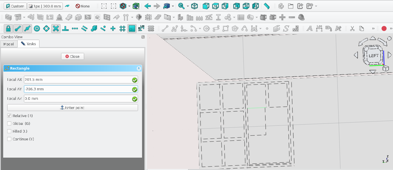
Create () a rectangle that is 201.5 mm in width and 251.3 mm in height starting from the point indicated above
Copy and move the rectangle such that it has a 30 mm gap between it and the original
Move the two (201.5 mm by 286.3 mm) 30 mm lower from the rectangles above them
Define icon
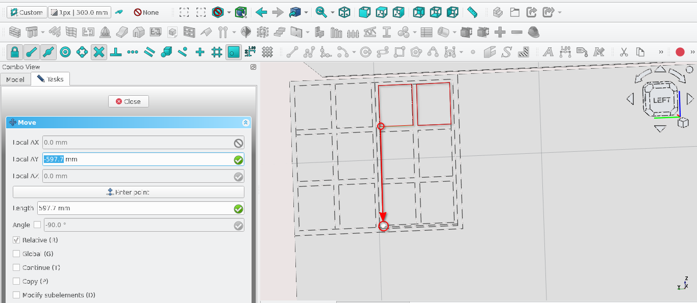
Move and copy the rectangles highlighted above by -597.7 mm
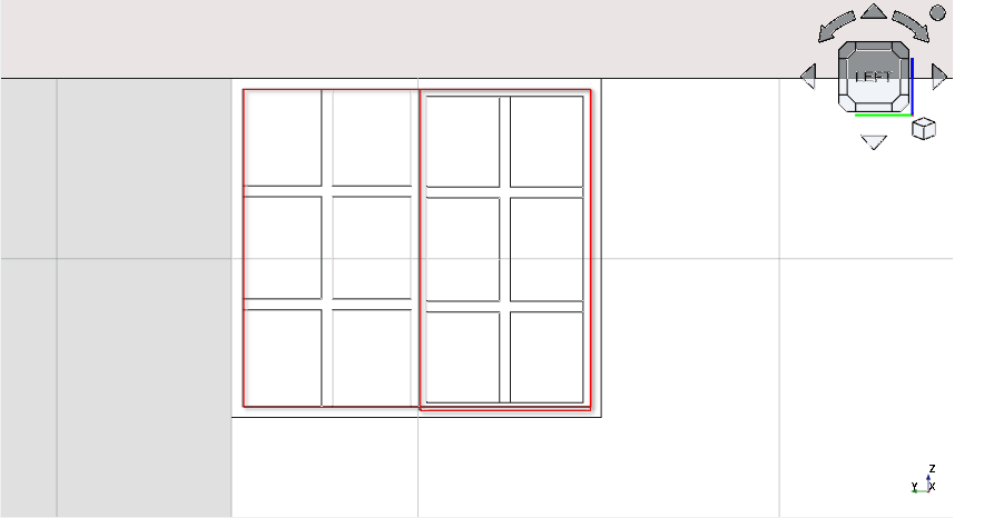
Delete the highlighted rectangles
Remember that for the purposes of creating a window or opening, lines should form closed loops and must not intersect
Select all the left over lines and create a sketch from the draft objects
Delete the wires/rectangles use to make the sketch
Creating Window W8
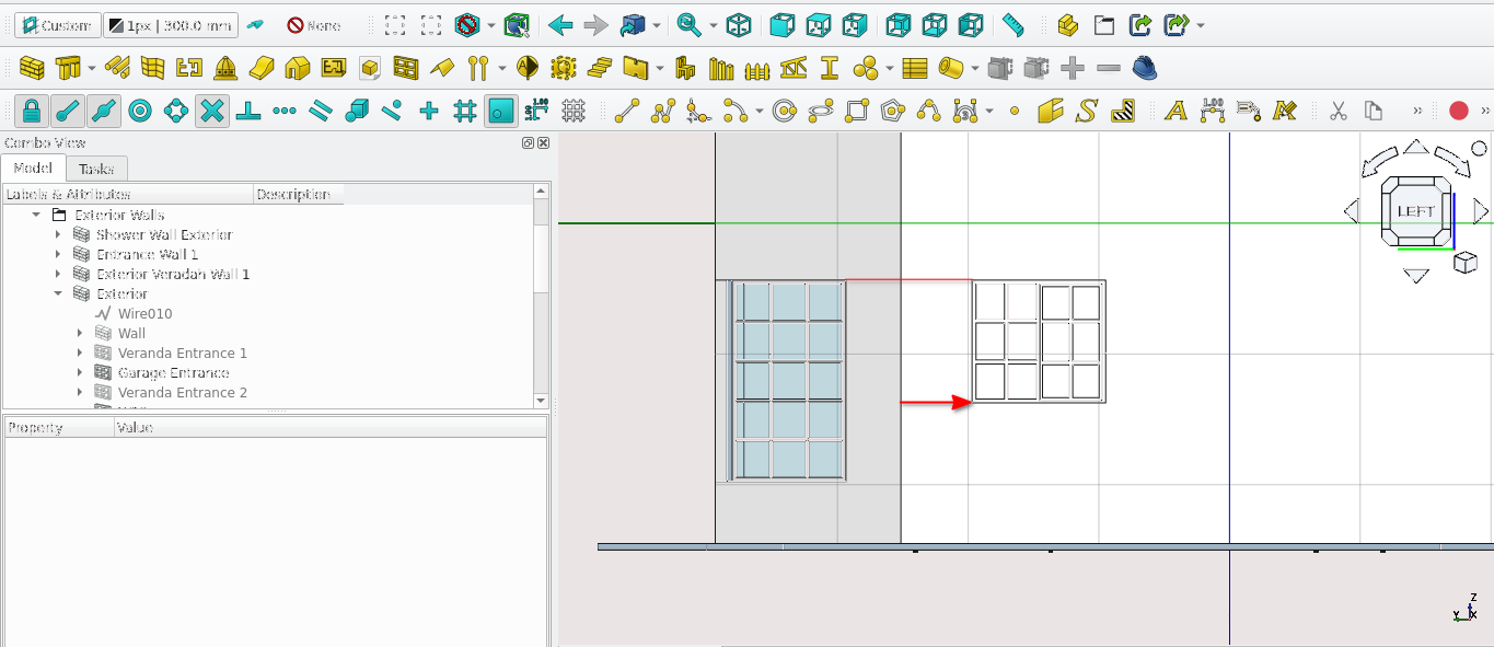
Align the sketch to the same height as the window in the above image
Move the sketch to the right by 545 mm
Create a window from the sketch
Rename the window to W7
Double-select the sketch in Combo View>Model
Navigate to Combo View>Tasks>Window elements
Under components select Default then the edit icon
Set the thickness field to 40 mm
Set the offset field to 90 mm
Set the ‘Type field’ to frame
Set the Name field to ‘outer frame’
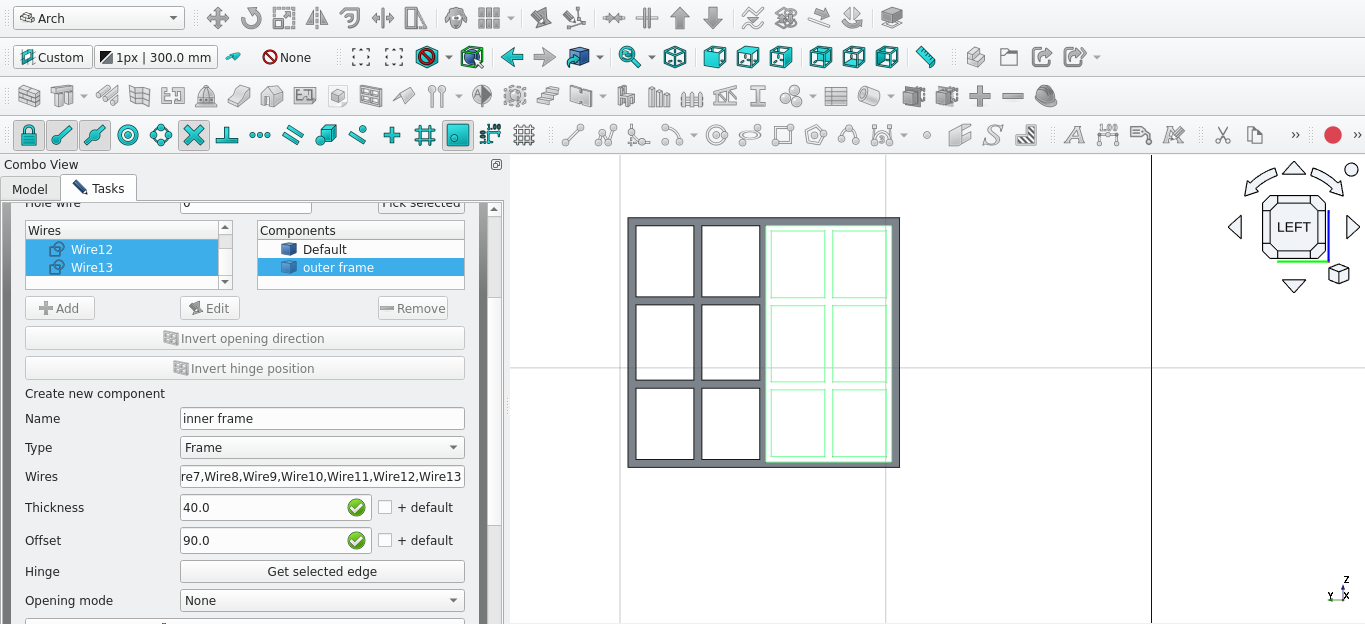
Select the add icon in Combo View>Tasks>Window elements
Use the above settings to create the inner frame of w7 select the appropriate wires
For the wire field
Set the name of the window to w5
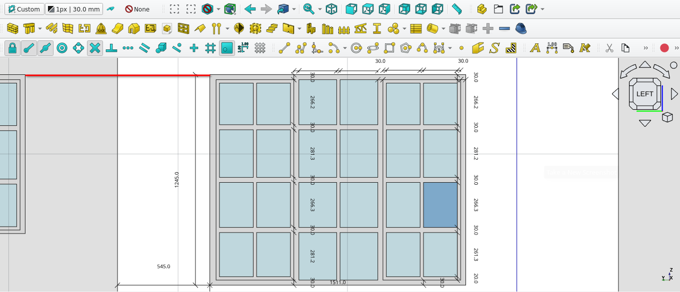
Create a window to the specifications above
Keep the window at the same height as the previous
Work flow tip: create draft objects>draft2sketch>Window Tool>add components
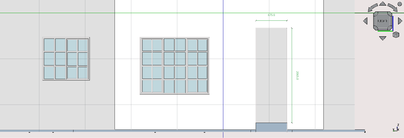
Hide ‘Shower wall' in Combo View>Model
Create an opening in the wall as shown above (use either the window tool or the remove component tool)
Rename the opening as ‘Shower Entrance’
Creating window w5
The window tool works by extruding existing sketches and assigning hinges to edges. Remember the procedure is:
Create wires with the specifications of the desired shape to be extruded
Delete the redundant wires
Select the wires then select the draft2sketch tool icon (
)
Select the sketch and press the 'W' then 'N' keys or select the Window icon
If the Sketch is correct (contains no duplicate lines or overlapping lines) the largest unclosed loop will create a window frame with 0 mm of thickness
Navigate to Combo View>Model and double-select the newly created window
Navigate to Combo View>Tasks under Window elements and select the default item under components
Modify the Name, Type, Wires (select the wires that make up the frame this is normally done for you if the sketch was created correctly), Thickness, Offset, Hinge and Opening mode as specified or desired
Select create component
If the Door or Window has sub-components that sit within the frame directly, select add under window elements
Enter and change the fields as required , remembering to select the appropriate wire
If the window or doors has no other frames within in it the process can be stopped here
If not, the inner frame must be created by selecting the add icon in Combo View>Tasks under Window Elements
Create the frame by selecting the the appropriate wires in the Wires list, set the appropriate hinge by selecting the appropriate edge on the sketch (then select Get selected edge) and lastly enter the required Thickness, Offset, Type and name Fields
Select create component
Select close to end the creation process
Navigate to Combo View>Model and select the newly created window
Navigate to Combo View>Model (with the window selected)
Under Window select the host field then select the wall you wish to place it into
To show the swing of the door in plan or top view set the symbolPlan Field to true
To show a symbol direction for elevations set the Symbol elevation to true
Create the window shown in the two images above this should be done on the ‘front’ view
Press 1 to navigate there quickly
Rename the window as ‘w5’
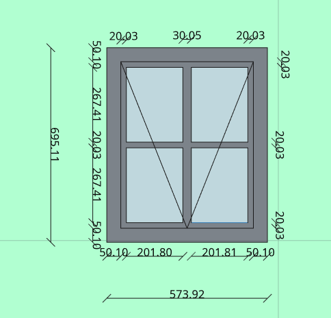
Create an
opening as shown above use the remove component tool (![]() ) or by creating window and hiding it
) or by creating window and hiding it
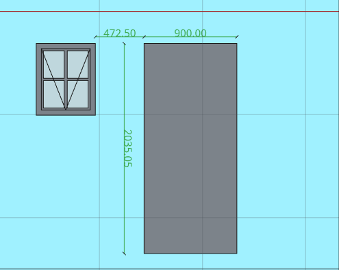
Create an opening as shown above use the remove component tool or by creating window and hiding it
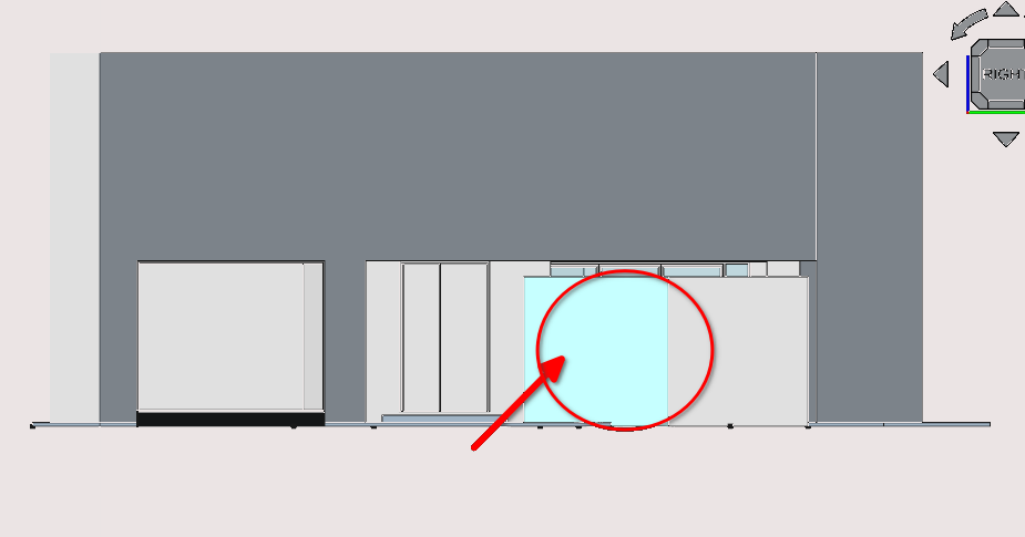
Press '3' to move to the front view of the building
Hide the verandah wall highlighted above and any objects that obstruct the view of the main wall
Select the wall and make it the active working plane
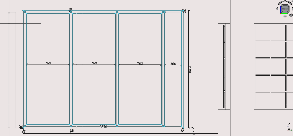
Create the folding doors shown above, the frame has a thickness of 30 mm
Select the wall and make it the active working plane
As overlapping lines tend not work well with sketches when creating windows, the work around is to create small spaces between said lines (0.01 cm)
Creating interior openings
Using premade windows
FreeCAD comes packaged with pre-made windows and doors that can be used
As seen in the basic 3D tutorial one can select the window tool icon without having 2D geometry selected
After selecting the tool one can set the parameters of the window or door by navigating to Combo View>Tasks and
Under point one can set the position of the door or window using coordinates the a more intuitive method is to select the wall you wish to add it to with the cursor
Under window options one can set the preset to be used as well as its dimensions
It is generally wise to make the face of the wall you wish to use the active plane and to have snap working plane on to ensure that the doors or windows normals are parallel to the face of the wall
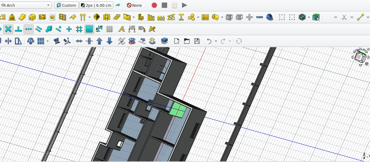
Using pre-made windows
Use the a height of 220cm and a width of 70cm for the doors
Use a height of 206.5 45 and a width of 45cm for the storage openings
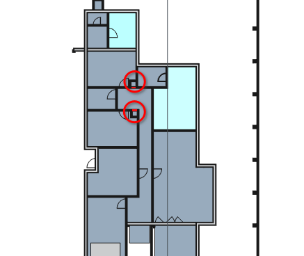
Using the Roof tool
basic work flow and parameters
The Roof tool can be activated via the short cut of pressing 'R' then 'F' or by selecting the Roof tool icon
It requires a 2D base object with a closed loop such as a wire or rectangle
The base 2D object should be drawn in an anti-clockwise direction or it will invert the normals of the 3D projection
Once created the properties of the roof can be modified by double-selecting the roof then navigating to Combo View>Tasks
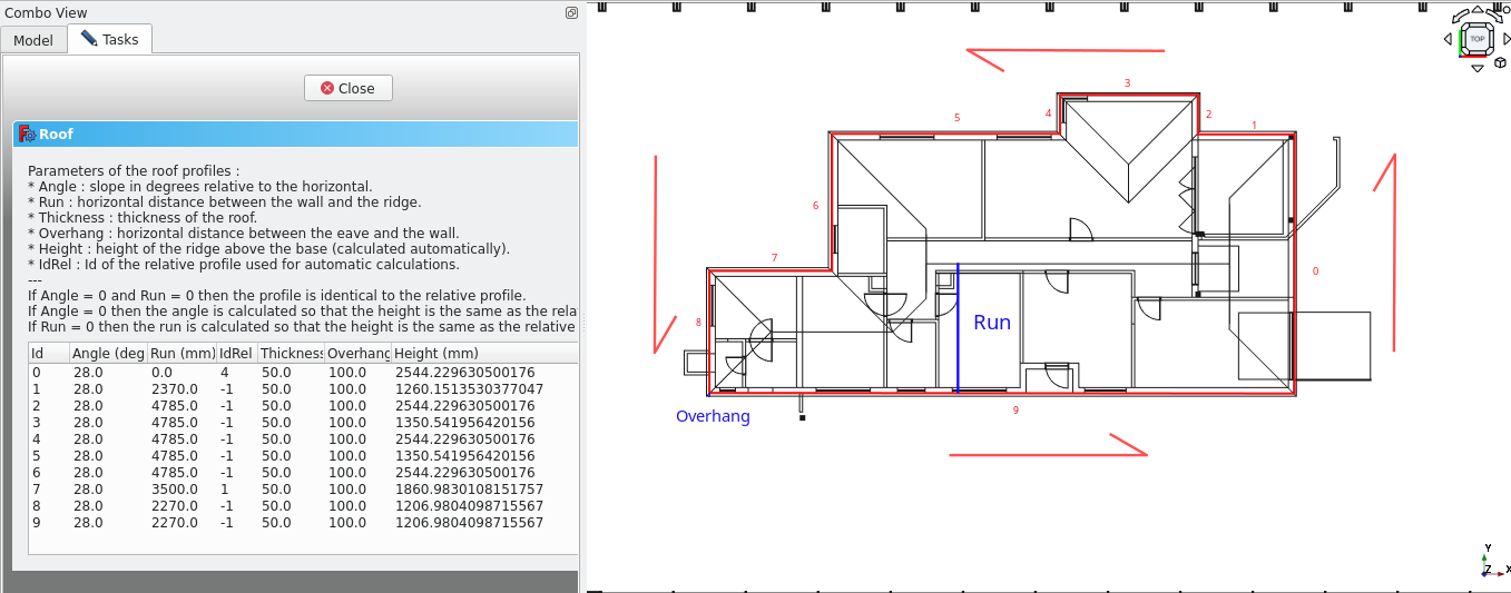
The image above gives an example of the Roof tool under Combo View>Tasks
Each row represents a roof plane, and each roof plane has a unique id starting from 0
The run is a horizontal distance from the start of the plane to where it meets with another plane (or the ridge)
The angle is the slope of the roof plane relative to planes horizontal
Thickness is how thick the particular plane is
Overhang is how far the roof plane extends beyond its original base line in a horizontal distance
id rel is the id of the another plane you wish to use for a plane to stop at or to use automatic calculations
Part 10: creating the roof
Creating the base object
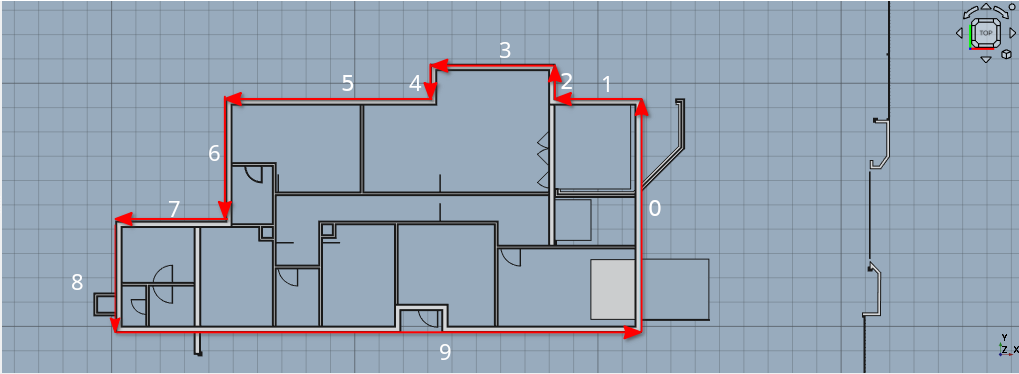
Press 2 to move to the top view or plan view of the building
Select all the walls and set their heights to 600 cm
Select the top face of the exterior walls then select the Active plane icon (
)Ensure that the Snap Working Plane icon (
) has been toggled onSelect the polyline tool and trace the image shown above
With the newly created wire selected press 'R' then 'F' or select the Roof tool icon (
)
Create the polyline in an anti-clockwise direction or the roof will appear inverted
Editing the properties of the roof
Navigate to Combo View>Model and double-select the newly created roof then go to Combo View>Task
Set the Angle property to 29°
Set the Overhang to 100 mm
For plane 0 enter the data in the image shown below
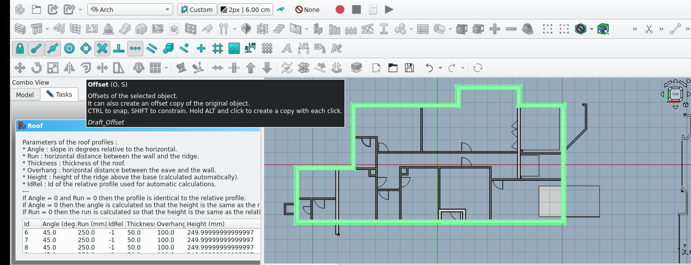
Double-select the newly created roof
Set the Angle property to 28°
Set the Overhang to 100 mm
Set the Thickness for each roof plane to 50 mm
Press ''Esc''
Select the polyline tool and trace the image shown above
Switch to Wireframe view by press 'V' then '3' or View>Draw style>Wireframe
Keeping the active plane as the top, draw the shape highlighted below using lines and polylines (you may use construction mode as this is for reference)
You can then measure the distance from the spine to the edge of the roof plane; this will give you the run of the roof plane (note that this method assumes all angles are the same)
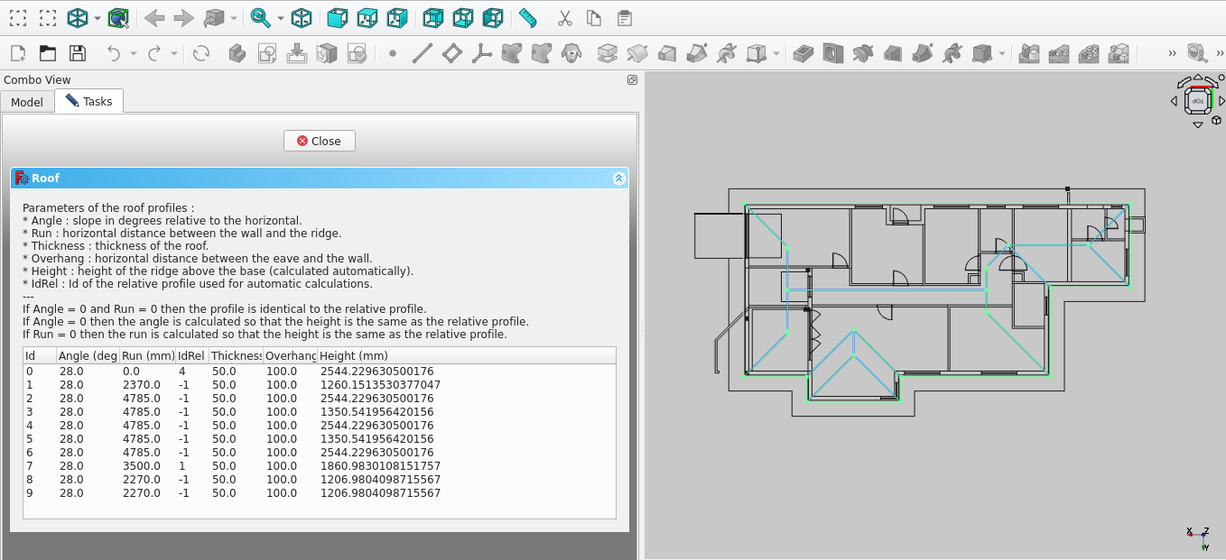
Double-select the roof and enter the details shown in the image above
As mentioned before you may obtain the run distance for the roof by measuring the distance from the predicted spine of the roof to the respective edge of the roof
Note to use 4 for the idrel (Id relative to) for the the number 0 plane. This forces the specified plane to meet or follow the profile of a specific roof plane. In this case, we wish for plane 0 to meet with plane 4
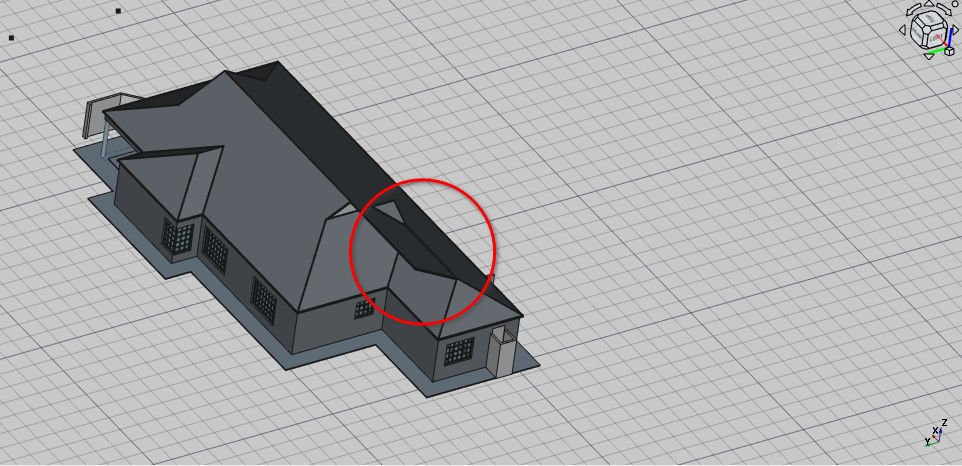
As you may have noticed, due to the roof plane being forced to meet with plane 4, the planes now clip into each other. To fix that, we have to use the Arch remove tool and the Arch cut with plane tool
Select the roof then select the clone tool as you can't use the roof to cut itself
Hide the original roof under Combo View>Model
Select the hidden roof while holding 'Ctrl' then select the Face shown in the image below
Select the Arch Cut with plane tool icon (
) under tasks for defining which side to cut option select front
then select ‘Ok’ or press 'Enter'
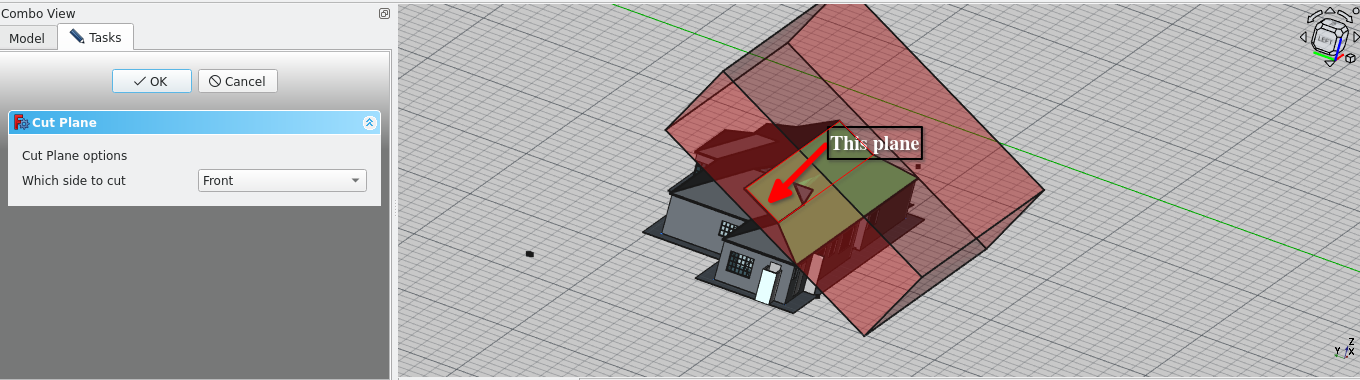
The next step involves creating 3D cubes parallel to the planes to use with the Arch remove tool
Select the roof then select the clone tool as you cannot use the roof to cut itself
Hide the original roof under Combo View>Model
Press 4 to got to the rear view and align the active working plane to the wall highlighted in the image below
Navigate to Combo View>Data with the rectangle selected and set its Make face property to true
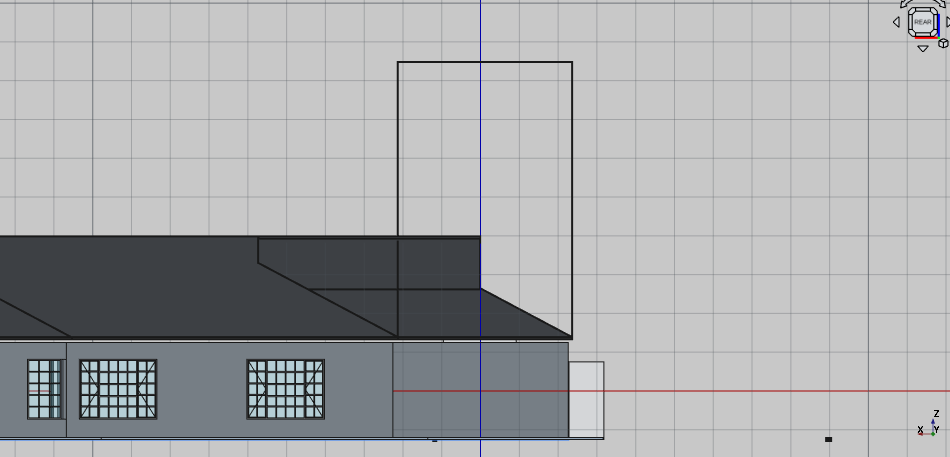
Press 6 to Navigate to the left view
Align the active working plane to the wall highlighted in the image below
Select the newly created rectangle and rotate it such that it is parallel to the roof plane
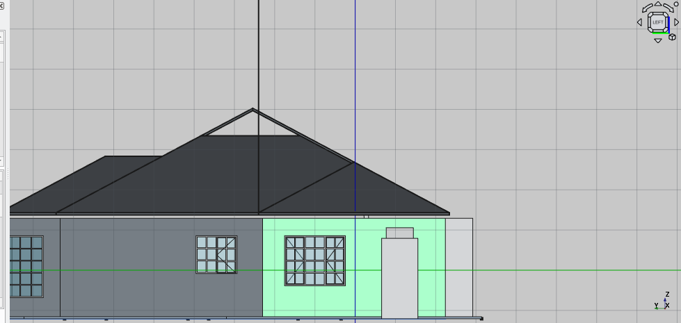
Orbit so that you can view the roof plane highlighted below
Make the the roof plane the active working plane
Select the rectangle and rotate it such that it is parallel to the roof plane edge as shown below
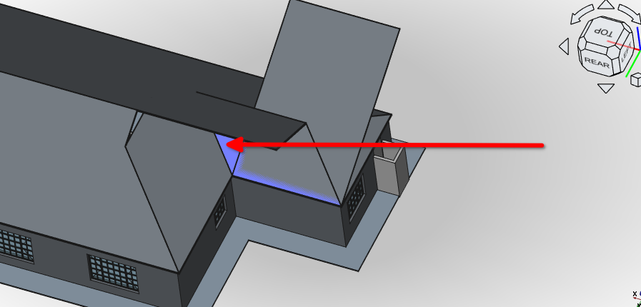
Select the rectangle and rotate it such that it is parallel to the roof plane edge as shown below
Extrude the rectangle using the trimex tool icon (
)Make sure to extrude the rectangle beyond the extents of the roof plane
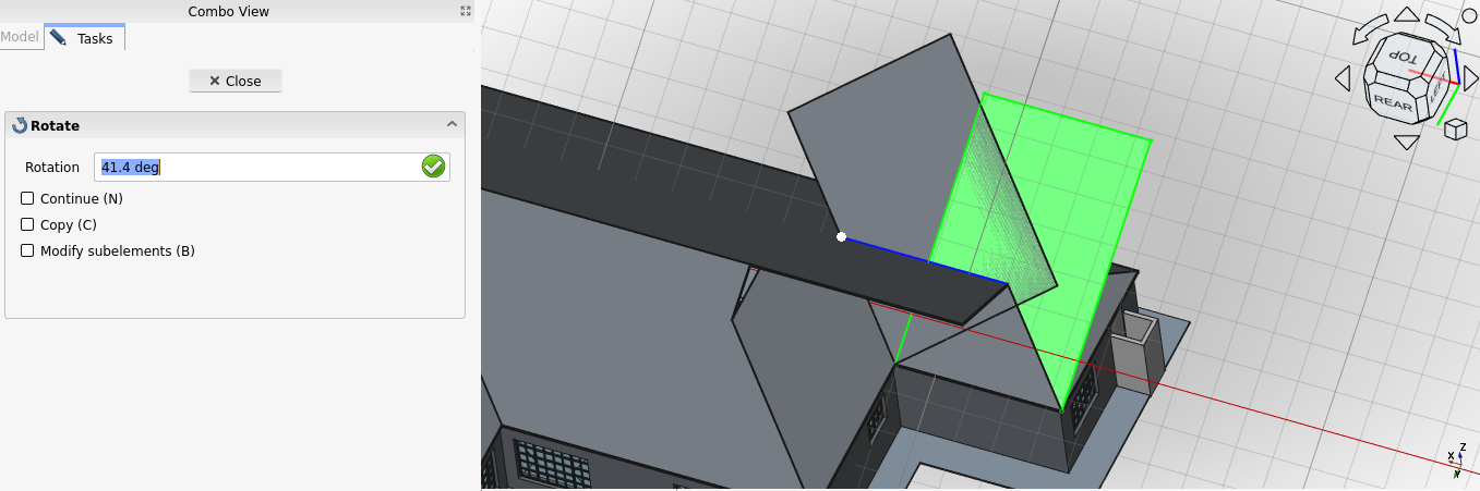
Extrude the face of the newly created extrusion shown in the image below
Extrude the rectangle using the trimex tool (
Make sure to extrude the rectangle beyond the extents of the roof plane
Select both the newly created extrusions then select the Upgrade icon (
)Select the newly created fusion then select the Roof tool icon or press 'R' then 'F'
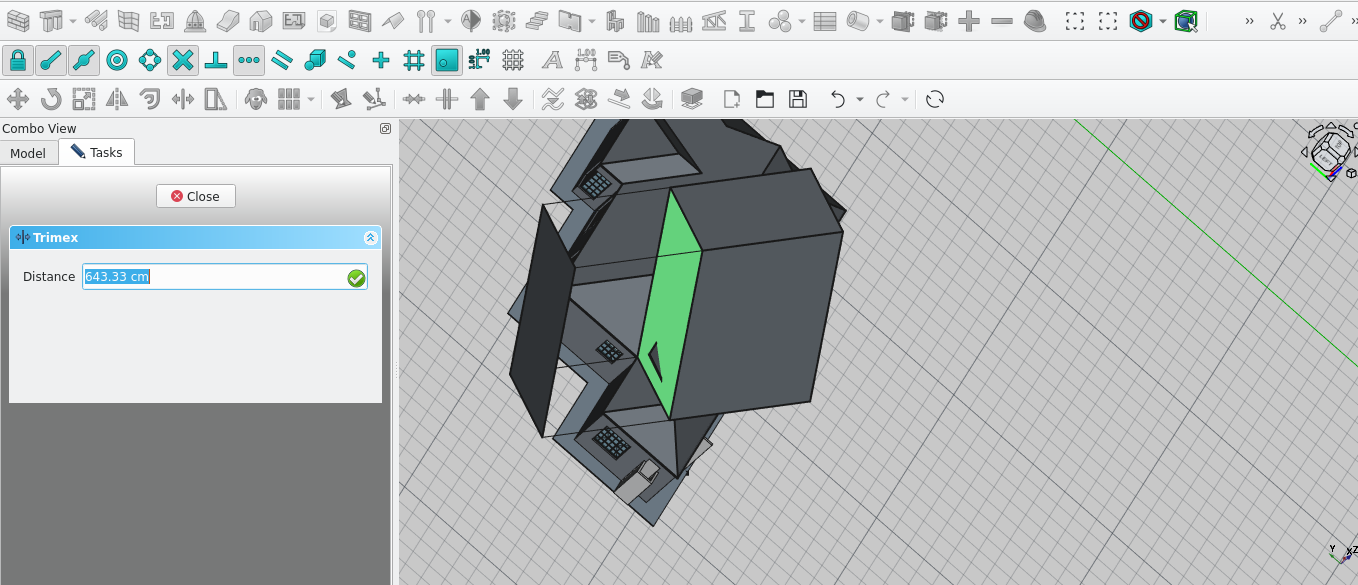
Extrude the face of the newly created extrusion shown in the image below
Extrude the rectangle using the trimex tool (icon)
Make sure to extrude the rectangle beyond the extents of the roof plane
Select both the newly created extrusions then select the Upgrade icon (Upgrade icon ()
Select the newly created fusion then select the Roof tool icon or press 'R' then 'F'
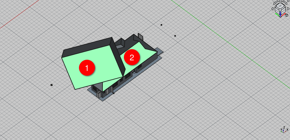
Select the newly created roof object then the original roof you wish to cut while holding 'Ctrl'
Select the arch remove icon
Select the block shaped roof object and press the space bar to hide it
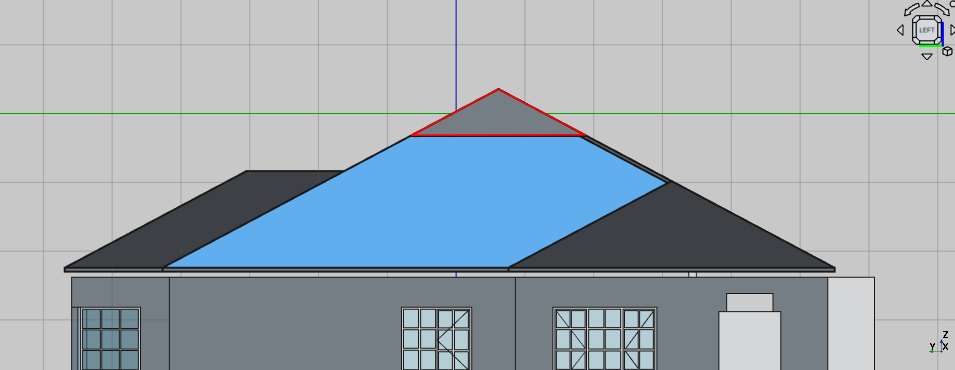
Create the shape shown above with the polyline tool
Select the newly created polyline and navigate to Combo View>Data
Set the Make face property to true
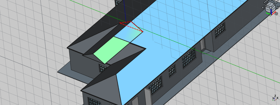
Orbit so that you can view the roof at an angle
Select the recently created polyline and extrude it as shown in the image above
Select the newly created extrusion and select the Roof tool icon
Select the newly created roof extrusion then select the main roof body while holding 'Ctrl'
Select the Arch subtraction tool icon
As you may have noted the arch objects generally have to be of the same type when removing or using objects from another or vice versa
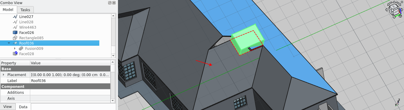
Select the roof plane shown in the image above and set it as the active working plane
Create a rectangle plane
Create a rectangle on the plane and place it
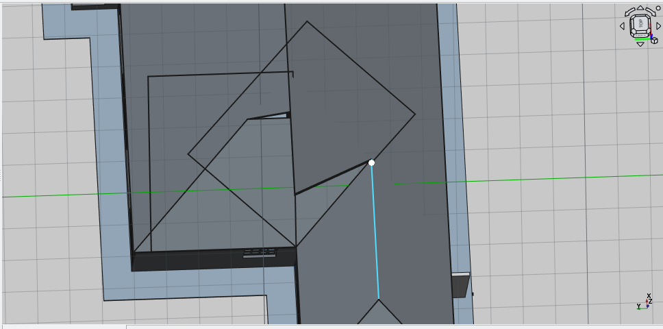
Press 2 to navigate to the top view and select the face highlighted and make it the active working plane
Create a rectangle of 2000 by 1000 mm
Select the rectangle and move it lower point of the rectangle to the point highlighted above

This concludes Tutorial 06
Freecad Architectural Work Tutorial