|
01 |
|
|||
Setting Up: Introduction To FreeCAD |
|||||
|
What is FreeCAD ? |
|
|||
|
Free CAD is a parametric 3D Modelling program with 2d Drafting capabilities. For this tutorial you will learn how to
|
|
|||
|
Start page |
|
|||
|
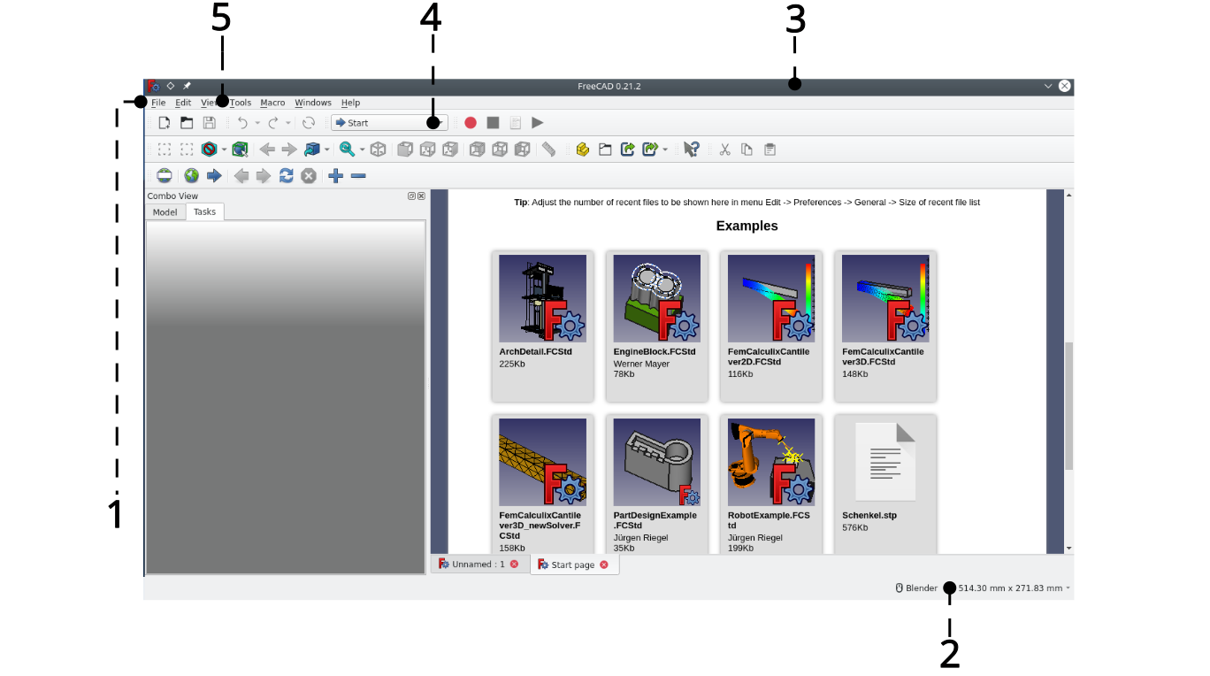
This is the starting page that appears when first starting FreeCAD. The table below explains each annotated item. This remains the same until the settings are changed. It displays example files that can be opened to show the capabilities of the software. The start page can also be called from >workbench selector (4)>start |
|
|||
|
|
|
|||
|
Menu items |
Description |
|
||
|
Combo view (1) is the default left-hand box on the screen |
The combo view consists of 2 tabs; Model and Tasks.
|
|
||
|
Navigation style (2) |
Displays the current selected way to: pan, zoom, select and rotate the view |
|
||
|
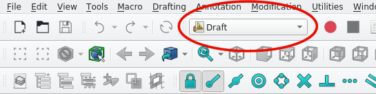
Current Work Bench (3) |
This displays the current work bench. A work bench is a set of tools used to perform certain tasks |
|
||
|
Tool Bar (4) |
Displays the current tools of the active work bench |
|
||
|
Drop Down Menu bar (5) |
Standard options |
|
||
|
Initial workbenches |
|
|||
|
Draft work bench |
|
This is a collection of 2D drafting tools , including; points, lines , poly lines, circles, other geometric shapes and the means to dimension and modify them |
|
|
|
Arch work bench |
|
Has some cross over with the draft work bench, it is a collection of tools that deals primarily with the creation of building components such as wall, slabs roofs and windows. |
|
|
|
Tech draw work bench |
|
This is a collection of tools used to place 2D drawings and views of 3D objects on to a virtual representation of a paper. Here, drawings from different workbenches can be scaled, rotated and further annotated |
|
|
|
Conventions And Shortcuts |
|
|||
|
Mouse Layouts |
|
|||
|
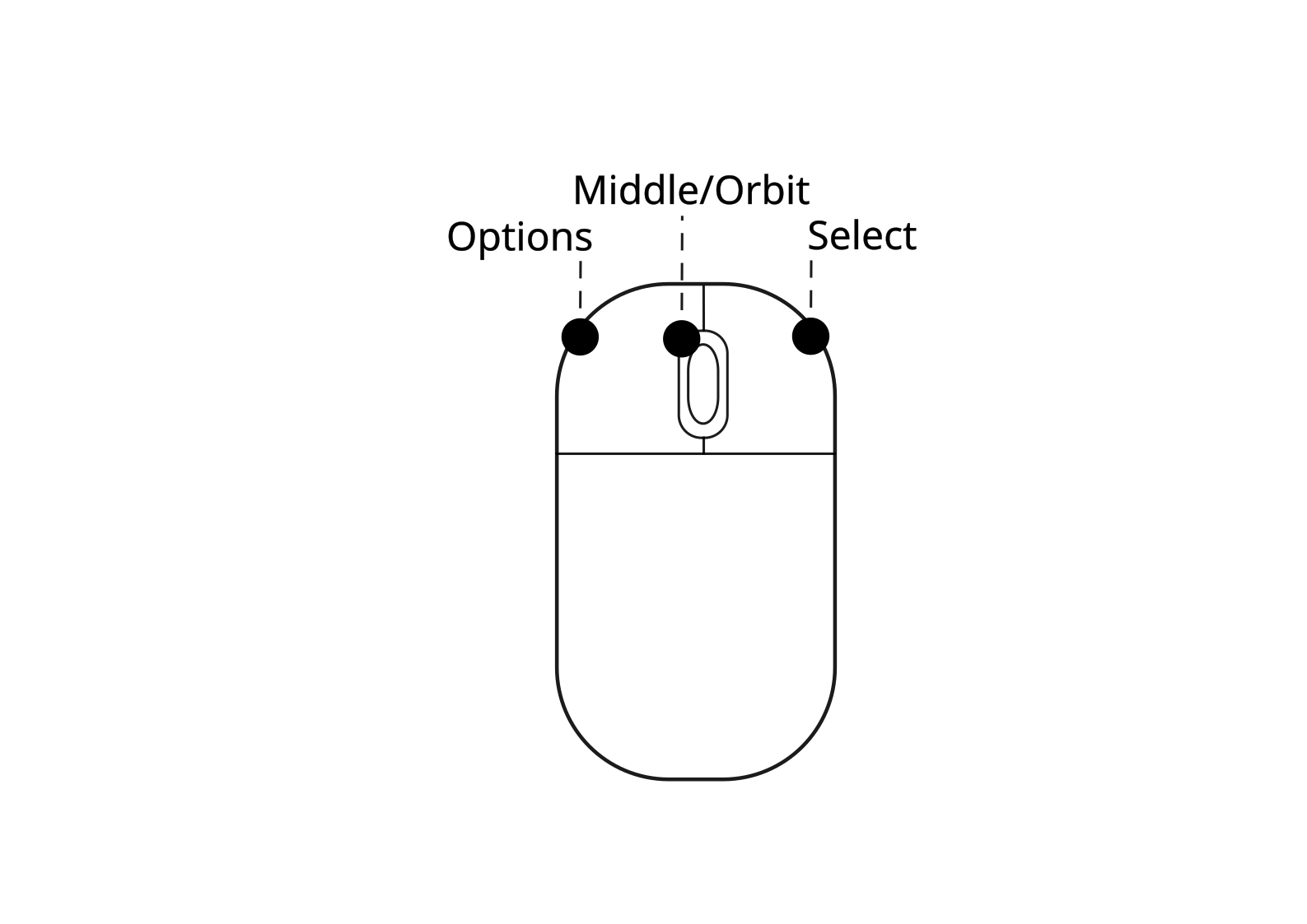
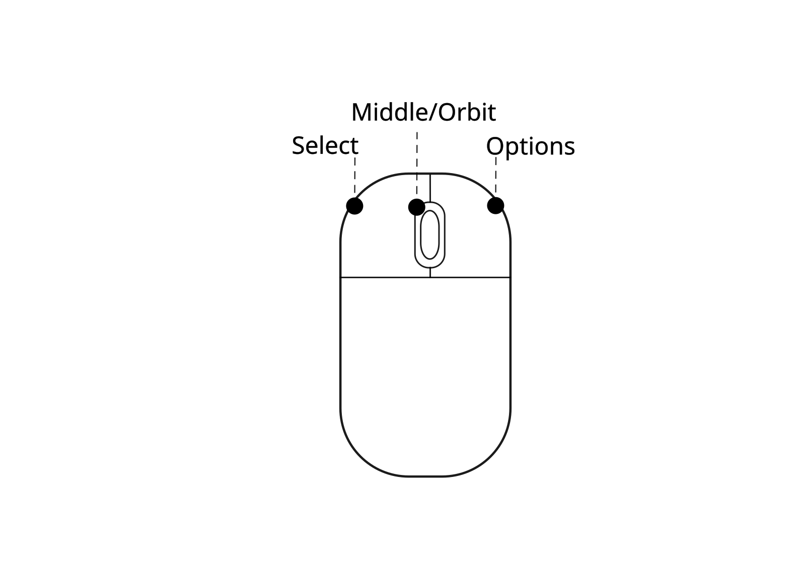
Left handed layout |
Right handed layout |
|
||
|
|
|
|
||
|
Keyboard |
|
|||
|
Function |
Command |
Icon |
Tips |
|
|
Navigation |
|
|||
|
Multi select |
Hold ‘Ctrl’ and select with the cursor |
- |
Click once and move mouse over objects. |
|
|
Box select |
‘Shift+E’ |
- |
Click once and move mouse over objects. |
|
|
Zoom in and out |
Ctrl + middle + (move mouse) |
- |
- |
|
|
Pan view |
Shift + middle (mouse move) |
- |
- |
|
|
|
|
|
|
|
|
Creating objects |
|
|||
|
Function |
Command |
Icon |
Tips |
|
|
General note |
|
|
All Draft tools are available in the Arch work bench |
|
|
Create Point |
Has no keyboard shortcut. Select it in the tool bar (arch and draft workbenches) |
|
Select once with the mouse when placing |
|
|
Create line |
Select the icon or press ‘L’ then ‘I’ |
|
Select the start and end with the mouse. |
|
|
Create polyline |
Select the icon or press ‘P’ then ‘Y’
|
|
The ‘/’ key undoes a point input. |
|
|
Create circle |
Select the icon or Press ‘C’ then ‘I’ |
|
The first selection selects the centre |
|
|
Create ellipses |
Select the icon or press ‘E’ then ‘L’ |
|
The first point determines its start and the second how long it is |
|
|
Create Arcs |
Select the arc icon in the tool bar, there are two ways to create an arc: selecting three points selecting a centre and radius then two points |
|
- |
|
|
Create rectangle |
Select the icon or press ’R’ then ‘E’ |
|
- |
|
|
Create polygon |
Select the icon or press ‘P’ then ‘G’ |
|
- |
|
|
Create beziér |
Select the icon. You may select each point manually |
|
You can create n curves and/or cubic curves |
|
|
Create b-spline |
Creates a multi point B spline. You can select each point where it bends |
|
- |
|
|
Modifying Objects |
|
|||
|
Move object |
Select the icon or press ‘M’ then ‘V’ and select the object you wish to move or vice versa Move an object by selecting a reference point then select a destination point (select using your mouse) |
|
You can select multiple objects using ‘box select’ or pressing selecting with the mouse while holding control |
|
|
Rotate object |
Select the icon or press ‘R’ then ‘O’ and select the object |
|
Rotate an object using a reference point |
|
|
Offset object |
Select the icon or press ‘O’ then ‘S’ or select the icon and select the object you wish to move |
|
This offsets objects depending on the position of the cursor |
|
|
Mirror object |
Select the icon or press ‘M’ then ‘I’ |
|
This mirrors an object across a line |
|
|
Trim object |
Select the icon or press ‘T’ then ‘R’ This shortens or increase the length of a line |
|
This can alternatively be a poly-line segment |
|
|
Hiding/revealing an object |
Press the ‘spacebar’ while item or items are selected in combo view>model |
- |
- |
|
|
Box select |
Select the icon or press Shift+’B’ then drag the cursor to pick up the items you wish to select |
|
- |
|
|
Box element select |
Select the icon or press Shift+‘E’ then drag the cursor to pick up the items you wish to select |
|
Selects particular parts of objects such as faces |
|
|
|
|
|
|
|
|
Snap points |
|
|||
|
Snap points exist on all geometries one creates. To activate snap points press Shift+’S’. The snap icon will appear as shown in the image to the right |
|
|
|
|
|
This indicates that Snap Lock is on. Pressing Shift+’S’ again toggles these snap points off |
|
|
|
|
|
|
|
|
|
|
|
End points |
|
This snaps to the end points and vertices of 3D and 2D objects |
|
|
|
Mid point |
|
This snaps to the mid point of a line |
|
|
|
Centre |
|
This snaps to the centre of shapes such as rectangles and circles |
|
|
|
Intersections |
|
This snaps to intersecting, meeting or overlapping geometries |
|
|
|
Parallel |
|
When creating lines this creates a snapping point parallel to an existing line or object |
|
|
|
Snap working plane |
|
Projects snap points onto the current active working plane |
|
|
|
Grid snapping |
|
This snaps the cursor to points on the grid |
|
|
|
Ortho snapping |
|
This snaps the cursor to vertical, horizontal or 45 degrees when drawing geometry |
|
|
|
|
|
|||
|
Preferences Menueferences Menu |
|
|||
|
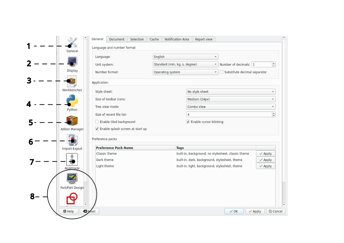
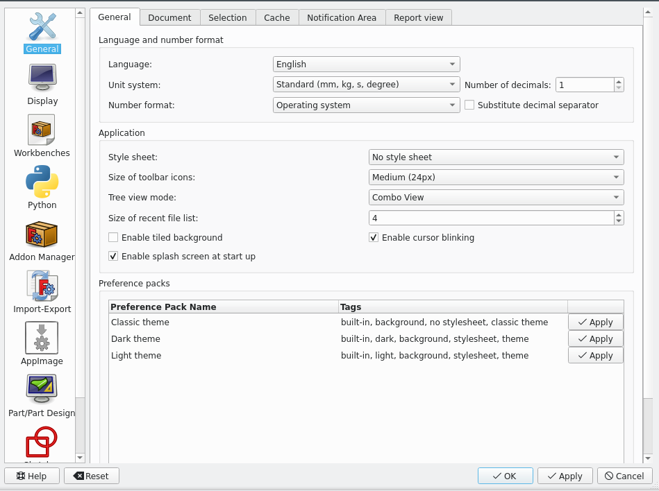
The Preferences menu displays the settings and defaults for work benches and other more General settings |
|
|||
|
|
|
|||
|
Items |
Function |
Tips |
|
|
|
General (1) |
To adjust the default units and language preferences |
- |
|
|
|
Display (2) |
Changes the rendering and colour settings |
For 2d drafting use a simple light grey colour for the background for good visibility |
|
|
|
Workbenches (3) |
General work bench options |
- |
|
|
|
Python (4) |
Can be used to create Macros and custom commands |
Macros can automate repetitive processes |
|
|
|
Add-on Manager (5) |
Can be used to add more workbenches |
Note that some work benches are still being tested |
|
|
|
Import- Export (6) |
Mainly going to be used to convert files to dxf, pdf and stl as well as importing these file types |
The c++ exporter/importer is faster but has less features than the python exporter/importer |
|
|
|
App Image (7) |
It is used to get updates for the FreeCAD Linux software file |
- |
|
|
|
Work Bench options (8) |
Contains a set of options unique to each work bench, such as defaults for objects |
Make sure the workbench you want to edit is active |
|
|
|
Setting up FreeCAD Defaults |
|
|||
|
|
|
|||
|
|
|
|||
|
|
|
|||
|
Navigation |
|
|||
|
|
|
|||
|
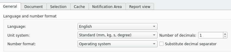
Step 3: General tab |
|
|||
|
Changing units |
|
|||
|
|
|
|||
|
|
|
|||
|
Changing colour settings |
|
|||
|
|
|
|||
|
Change the Background colour from the default linear gradient to a simple colour
|
|
|||
|
This concludes Section 01 of the tutorial |
|
|||
Freecad Architectural Work Tutorial |
|||||