02
Tutorial 2 Part a: Creating 2D Geometry
Tutorial 2 Part aa: Key Terms
vertex/vertices
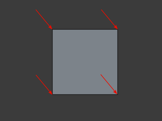
A point where multiple edges meet (There must be more than 1 edge)
edge/edges
Lines that surround a face
face/faces
A flat 2D face that is surrounded by edges and vertices
Tutorial 2 Part ab: Starting a new file: Step 1
Creating documents and preparing a file

Select >file>new (This creates a new document).
Select the work bench icon (
 ) from the drop down menu shown above. Select the Draft work
bench. When first starting, the default work bench will be the
Start work bench
) from the drop down menu shown above. Select the Draft work
bench. When first starting, the default work bench will be the
Start work benchSave this new file using Save As (remember to save consistently)
When saving, type Tutorial II in the file name field then select Save (you can quickly save by pressing Ctrl+S )
Though FreeCAD has an auto save feature enabled by default, please save regularly
Setting up Snap Points and the Working Plane
Set the view to the top by pressing 1 on the keyboard. You may also select the view via the cube in the top right corner of the screen
Select the active Working Plane to Top (This ensures objects are only drawn in one plane). Select this icon (
 ) then navigate to Combo View>Tasks and under Working Plane
setup, select Top (X,Y) (
) then navigate to Combo View>Tasks and under Working Plane
setup, select Top (X,Y) (
 )
)To lock all the the snaps, select the Snap Lock icon (
 ) (this function can be toggled on and off by reselecting the
icon)
) (this function can be toggled on and off by reselecting the
icon)To snap new geometry to vertices select the Snap End Point icon (
 )
)
To ensure that all new objects are created on the current active working plan, select the Snap Working Plane icon (
 )
)
Tutorial 2 Part ac: Creating points: Step 2
How to create points
Points can be made in the following ways:
Select the Point icon in the tool bar menu (
 )
)
You will note that Combo View changes to the Tasks sub-item (the same applies whenever a new object is being created) Then proceed to select your required sub-sub-items under Tasks.
You may then place the point in the following ways:
Select anywhere in the drawing plane (press the select button on the mouse anywhere) to place a point arbitrarily
Enter coordinates in the Combo View>Tasks
Use Snap Points to define the position on another object (such as a grid , shape or wire)
Task 1
For task 1, create a point labelled A at the origin. As noted above, there are three options, firstly Arbitrary, secondly using the Combo View, and lastly using Snap Points. The instructions below explain how to perform this task using those three options.
Arbitrary placement of Points and modification after creation

Select the point icon (
)Select anywhere on the screen
Select the newly created point A
Navigate to Combo View>Model
Select the Combo View>Model>Data tab then set X to 0 and Y to 0 (No change to Z as we are working only on the Top Plane)
When successfully created, delete this new point and proceed to the next option
Combo View point creation
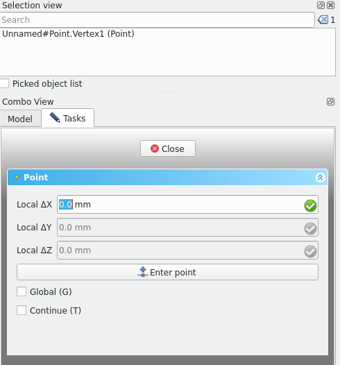
Select the point icon (
)
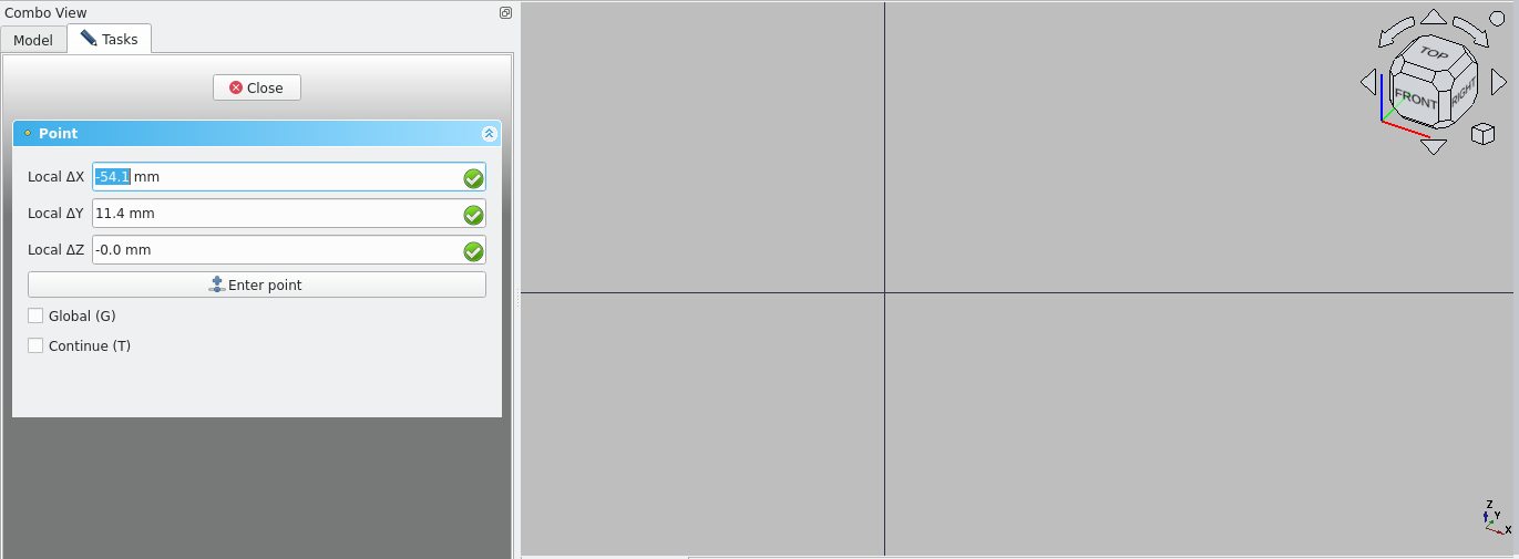
Navigate to Combo View>Tasks
For Local ΔX enter 0 mm, then press the Tab key, For Local ΔY enter 0 mm then press the Tab key, leave Local ΔZ as 0 mm then lastly press enter on the keyboard or select Enter point under Combo View>Tasks to confirm
Delete this point as the next step will recreate the point using a different method (you can do this by navigating to Combo View>Model, selecting the point and pressing the Delete key)
Creating a Point using Snap Points
Select the Point icon
Select Snap to Grid icon (
 )
)Select the Grid icon (
 )
)Select the intersection of the red and green grid lines
When hovering mouse, Combo View>Tasks>Point should read 0 mm for Local ΔX, Local ΔY and Local ΔZ
Navigate to Combo View>Model and select the newly created point then press F2 on the keyboard to rename it, type in A
Tutorial 2 Part ad: Creating lines: Step 4:
Press L then I on the keyboard or select the Line tool icon (
 )
)Navigate to Combo View>Tasks; Then proceed to select your required sub-sub-items under Tasks
You may then place the point in some of any of the following ways:
Select anywhere in the drawing plane (press the select button on the mouse anywhere) to place the first point arbitrarily then select anywhere on the drawing plane again to select the second point
Enter coordinates in the Combo View>Tasks (Enter the coordinates of the start point then enter the coordinates of the end point)
Use Snap Points to select the start point and then end point by first hovering the mouse on an intersection of edges or a point on another object (This may include items such as the grid, shapes or wires)
Task 2
Create a line from the origin at length 1000 mm, 45°. There are three options; Firstly arbitrary, secondly using the Combo View and thirdly using Snap Points. The following instructions explain how to perform this task using these three options: attempt each method before advancing
Arbitrary line creation
Press ‘L’ then ‘I’ or select line icon (
)Select first point anywhere
Select second point anywhere else
Select the line if you wish to adjust it using the steps below:
Navigate to Combo View>Model
Go to Model>Data and property Start then expand the Start data by clicking the adjacent arrow
For x, y and z enter 0 mm. This will adjust the line matching the new coordinates
Go to Model>Data and property End then expand the End data by clicking the adjacent arrow
For x and y enter 1000, for z enter 0. This will adjust the line to match the desired coordinates
Delete the line if desired
Combo View line creation
Navigate to Combo View>Tasks
Press ‘L’ then ‘I’ or select line icon (
)For x, y and z enter 0 mm
Select enter point
For length enter 1000 mm
Select the angle option (this locks in the angle)
Enter 45°
Press Enter key
Delete the line if desired
Creating a line using Snap Points
Press ‘L’ then ‘I’ or select line icon (
)Hover over the created point ‘A’ in the points exercise
The Snap Point icon appears (
 )
)Select that with your mouse
Move the cursor until the Snap Ortho icon appears (
 )
)Move the cursor diagonally to a grid intersection and hover over that until the Snap Grid icon (
 ) appears
Select that icon to complete your line
Notes: in actual practice these methods are mixed and matched where appropriate. To modify an object you must select it before going to edit the data
Tutorial 2 Part ae: Creating polylines: Step 5
Task 3
Create a polyline with three segments
Each segment should be 2000 mm long and at 90° to each other. The starting point should be the point ‘A’ from the points exercise

Creating polylines with the Combo View
Press ‘P’ then ‘Y’ or select the polyline icon (
 )
)
Navigate to Combo View>Tasks and go to Polyline
For Local Δx, Δy and Δz enter 0
Press Enter key
For Local Δx enter 0 mm
For Local Δy enter 2000 mm
Leave local Δz as default
Press Enter key or select Enter point to create first segment, then repeat:
For Local Δx enter 2000 mm
For Local Δy enter 2000 mm
Leave local Δz as default
Press enter key or select Enter point to create second segment, then repeat:
For Local Δx enter 0 mm
For Local Δy enter -2000 mm
Leave local Δz as default
Press Enter key or select Enter point to create third segment
Press Esc or select Close with the cursor
Delete the Polyline if desired
Drawing polylines arbitrarily
Press ‘P’ Then ‘Y’ or select the polyline icon (
)Navigate to Combo View>Tasks then go to Polyline
Select anywhere on screen 4 times then press Esc key or select Close. To modify the polyline:
Firstly, navigate to Combo View>Model, select the newly created wire, select the Downgrade icon (
 ) or press ‘D’ then ‘N’. Do this twice while the object
is selected
) or press ‘D’ then ‘N’. Do this twice while the object
is selectedThis creates 3 independent edges
Secondly, press U then P or select the upgrade icon while each is selected
This creates three lines
Select one of the lines
Combo View>Model>Data and click in data field of property>Start
For x,y and z enter 0.0mm
Navigate to Combo View>Model>Data and click in data field of property >End
For x enter 2000 mm
For y enter 0 mm
For z enter 0 mm
Select another of the lines
Navigate to Combo View>Model>Data and click in data field of property >Start
For x enter 0 mm
For y enter 2000 mm
For z enter 0 mm
Navigate to Combo View>Model>Data and click in data field of property >End
For x enter 2000 mm
For y enter 2000 mm
For z enter 0 mm
Select the last unmodified line
Navigate to Combo View>Model>Data and click in data field of property >Start
For x enter 2000 mm
For y enter 2000 mm
For z enter 0 mm
Navigate to Combo View>Model>Data and click in data field of property >Length
Enter 2000 mm
Press ‘Shift’+’E’ and box-select the 3 lines
Press ‘U’ then’ N’ or select upgrade
Delete the polyline if desired
Drawing polylines while using Snap Points
Turn on the following Snaps; Snap Grid (
), Snap Ortho (
) and Snap End point (
)Press ‘P’ then ‘L’
As each box in the grid is pre-configured to 1000 mm by 1000 mm
Select at the origin, then select two grid units up from the origin
Tutorial 2 Part af: Creating circles: Step 6
Task 4
Create a circle centred on the origin
Creating a circle with the Combo View
Press ‘C’ then ‘I’ or select the circle tool (
 ) in the tool bar
Navigate to Combo View>Tasks
For ΔX enter 0 mm
For ΔY enter 0 mm
For ΔZ enter 0 mm
Press Enter or select Enter point
For the radius
Enter 2000 mm
Press Enter
Delete the Circle if desired
Creating a circle arbitrarily
Press ‘C’ then ‘I’ or select the circle tool (
) in the tool barSelect the first point (anywhere); This will be the circle centre
Select anywhere with the mouse again; This will be the circle radius
If you want to edit the circle, navigate to Combo View>Model>Data
Under Data>Draft click in the data field of property>Radius and enter 2000 mm
Then click in the desired sub-sub-item data fields of property>Base; Go to placement then position
For position x enter 0 mm
For position y enter 0.0mm
For position z enter 0 mm
Creating a circle with Snap Points
Turn on end point Snap (
)Turn on Grid Snap (
)Type in ‘C’ then ‘I’ or select the circle icon (
)Hover the mouse over the point previously created
The Snap Point icon (
) will appearSelect it with your mouse, while it is visible during hover
Move your cursor away from the circle centre so that the radius shown in the Combo View is 2000 mm
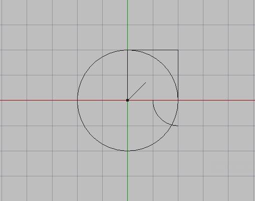
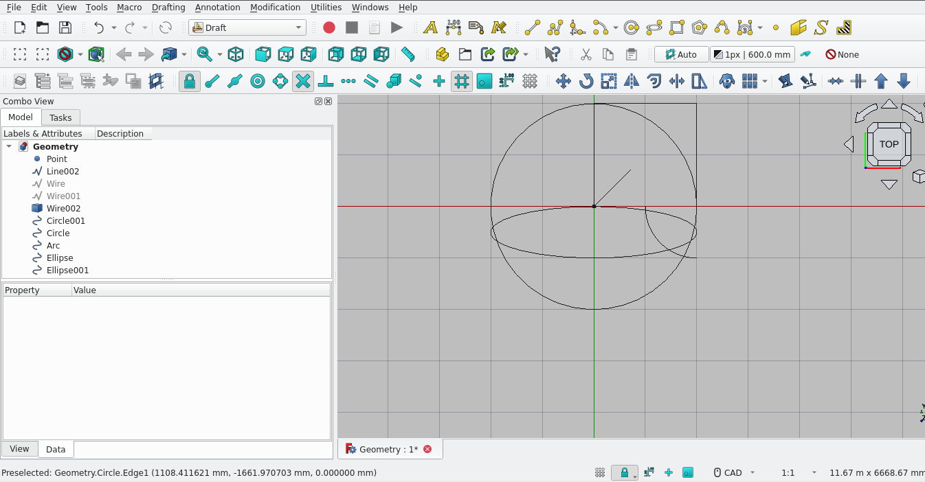
Selecting the bottom right corner of the previously-created polyline creates a circle of radius 2000 mm
Tutorial 2 Part ag: Creating arcs: Step 7
Task 5
Make an Arc with a centre at coordinates x=-2000mm, y=0 mm, z=0.0mm, a radius of 1000 mm, a start angle of 20° and an aperture angle (ie the end of the arc) of 80°
note:The arc tool is useful when showing the swing of a door in a floor-plan
Using the Combo View to create an arc
Select the Arc icon (
 )
)Navigate to Combo View>Tasks and select the data fields under Arc
For Local Δx enter 2000 mm
For Local Δy enter 0 mm
For Δz accept default 0 mm
Select Enter point with mouse or press Enter
For the radius enter 1000 mm
Enter ‘20’ for the Start angle
Press Enter
Enter ‘80’ for the Aperture angle
Press Enter
Creating an arc arbitrarily
Select the arc icon (
)Select on the screen 4 points; The first is for the centre point Position, secondly for the Radius, thirdly for the Start angle and lastly for the Aperture angle
If you wish to modify the arc, select the arc
Navigate to Combo View>Model>Data
Under Data>Draft
Select data field for Radius and type in 1000 mm
Select Start (First) angle and type in 20
Select End (Last) angle and type in 80
Under Data>Base select data fields under Placement
Angle should = 20
Position should be
X=2000 mm
Y= 0 mm
Z=0 mm
Delete arc if desired
Creating an arc using Snap Points
Turn on Grid Snap (
)Select the arc icon (
) in the tool barSelect the bottom-most intersection of the circle and the previously created polyline (2000,0,0)
Select 1 square away (radius of 1000 mm)
Hover your cursor over a grid square away from the the radius ( the start angle in the Combo View should read 90
Select that point with your mouse when the grid Snap symbol appears
Select a point inside the circle 1 grid square away from the radius of the arc
(be sure to move your cursor anti-clockwise)
Tutorial 2 Part ah: Creating ellipses: Step 8
Task
Create an ellipse that intersects with the circle arc and goes through the origin
Using the Combo View to create ellipses
Using the Combo View to create ellipses
Press ‘E’ then ‘L’(
 )
)Navigate to Combo View>Tasks> ellipses
For Local Δx enter -2000 mm
For Local Δy enter 0 mm
Leave local Δz as default
Select Enter point or press Enter
For Local Δx enter 4000 mm
For Local Δy key in -1000 mm
Leave local Δz as default
Press Enter or select Enter point
Arbitrary creation of an ellipse
Press ‘E’ then ‘L’(
)Select a starting point
Select a ending point
Select the ellipse
If you wish to modify the Ellipse, follow the instructions below:
Navigate to Combo View>Model>Data
Go to Draft; for minor radius enter 500 mm
Go to Placement and select small arrow next to position
For x enter 0 mm
For y enter -500 mm
For z enter 0 mm
Using Snap Points to create an ellipses
Make sure grid Snap Points are on
Press ‘E’ then ‘L’(
)Hover the cursor over a point outside the created circle
From the origin select a point on the grid 2 grid units to the right
Select it with the cursor
From the origin select a point 2 units to the left and 1 unit down from the origin.
Tutorial 2 Part ai: Creating polygons: Step 9
Task
Create a regular polygon with 6 sides that sits inside the circle. This tool is useful for creating the basis for the external walls of a building quickly
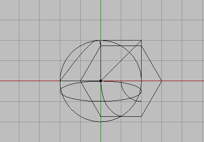
Creating polygons using the Combo View
Press ‘P’ then ‘G or select the Polygon icon (
 )
)Navigate to Combo View>Tasks
The coordinates entered next define the centre of the Polygon
For Local Δx key in 0 mm
For Local Δy key in 0 mm
Leave Δz as default
Select Enter point or press Enter
For sides, enter 6
For radius (on circle of outside points of Polygon), enter 2000 mm
Tutorial 2 Part aj: Creating B-splines: Step 10
Task
Create a B-spline that connects a vertices the point at the origin and another vertices
B-splines are useful for creating more organic designs.
Creating B-splines using the Combo View
Press ‘B’ then ‘S’ or select the B-Spline button (
 )
)Combo View>task Select the ellipse
For Local Δx enter -2000 mm
For Local Δy enter 0 mm
Leave local Δz as default
CH Update this text
This concludes Tutorial 02
Freecad Architectural Work Tutorial