03
Tutorial 03 (2 Part a): Creating 2D Geometry
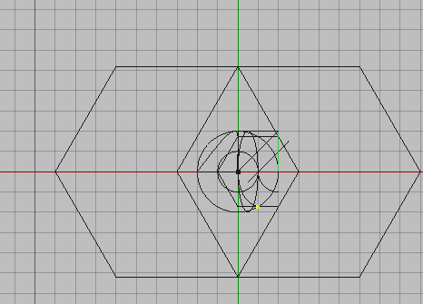
Tutorial 03 (2 Part a): Using the trim tool: Step 11
Task
Extend the 45 degree line to the edge of the circle.
Using Combo View with the Trim tool
Select the line on the side you wish to extend( the side closer to the circumference of the circle
Press ‘T’ then ‘R’ or select the trim icon (
 )
)Enter 1000 mm
Press Enter
Trimming arbitrarily
Select the horizontal line
Press ‘T’ then ‘R’ or select the trim icon (
)Move the mouse outside of the circle top right
To flip the Trim press & hold Ctrl+Alt before selecting with mouse as described next
Select with your mouse
Select the line
Combo View>Model>Data
Select length
Make it 2000 mm
Trimming with Snap Points
Select Snap end point (
 )
)Select the Snap intersection (
 )
)Select the diagonal line
Press ‘T’ then ‘R’ or select the trim icon (
)Move the cursor past the square and select
While holding the Ctrl key
Select the line again
Enter ‘T’ then ‘R’
Move the cursor while holding control
Select with your mouse when the line intersects with the circle
Tutorial 2 Part bb: Using the move tool: Step 11
Task
Move the six sided Polygon 1000 mm along the x axis
Using the Combo View and Move tool
Select the six sided Polygon with the cursor
Press ‘M’ then ‘V’ or press the Move icon (
 )
)Select the reference point
In this case;
Navigate to Combo View>Tasks and enter the following
For Local ΔX enter -2000 mm
For Local ΔY enter 0 mm
Leave Local Δz as default
Press ‘X’
For Local ΔX enter 1000 mm
Press Enter
Press Ctrl+‘Z’ to undo the above if desired
Using the Move tool arbitrarily
Select the six sided Polygon
Press ‘M’ then ‘V’ or press the Move icon (
)Press ‘X’ to restrict to the x-axis
Select a reference point anywhere
Select anywhere to the right of the Polygon
Press Ctrl+’Z’
Using Snap Points and the Move tool
Toggle Snap Grid on (
 )
)Toggle Snap Point on
Select the six sided Polygon
Press ‘M’ then ‘V’ or press the Move icon (
)Hover your mouse over the right-most vertex of the Polygon
When the Snap Point icon (
 ) appears, select with your mouse
Press ‘X’
Move the cursor one grid unit from the previously selected point
When the Snap Grid icon (
 ) appears as you hover above an intersection on the grid, select
with your mouse
) appears as you hover above an intersection on the grid, select
with your mouse
Tutorial 3 Part bd: Using the scale tool: Step 12
Task
Scale the six sided Polygon by a factor of three
Using Combo View and scale tool
Select the hexagon
Press ‘S’ then ‘C’ or select the Scale icon (
 )
)Navigate to Combo View>Tasks
Select Uniform scaling
Select Working Plane orientation
Select create Clone (the Clone function will be explained later in the tutorial)
For scale factor x enter 3
Note that this sets the y and z scale factors to 3 as well
This is because Uniform scaling was selected
Press Ctrl+’Z’ to undo the above
Using the Scale tool arbitrarily
Select the hexagon
Press ‘S’ then ‘C’ or select the Scale icon (
)Navigate to Combo View>Tasks
Select Uniform scaling
Select Working Plane orientation
Select create Clone (the Clone function will be explained later in the tutorial)
For scale factor x enter 3
Note that this sets the y and z scale factors to 3 as well
This is because Uniform scaling was selected
Scaling with Snap Points
Toggle Snap Grid on (
)Select the hexagon
Press ‘S’ then ‘C’ or select the Scale icon (
)Select one of the vertices on the hexagon
Select a point one grid unit from the vertices you first selected in x+ direction
Select a second point two grid units in x+ direction from the selection you just made
This makes the scale factor 3
Tutorial 2 Part be: Using the mirror tool: Step 13
Task
Create a mirror image of the enlarged hexagon, using a vertical line through the origin.
Using the Combo View and Mirror tool
Select the enlarged cloned hexagon
Press ‘M’ then ‘I’ or select the mirror icon (
 )
)Navigate Combo View>Task>Mirror
To define the first point of the mirror line carry out the next three items
For Local Δx enter 0 mm
For Local Δy enter -10 mm
Leave Δz as default
As each number is entered, press Enter
To create a second point defining the Mirror line
For Local Δx enter 0, then for Local Δy enter 10
When the Mirror line is thus defined, the earlier-selected object (enlarged cloned hexagon) is immediately mirrored about the line
Press Ctrl+‘Z’ to undo the above
Creating a Mirror of an object arbitrarily
Select the enlarged cloned hexagon
Press ‘M’ then ‘I’ or select the Mirror icon (
)Select any two points with your cursor to define the Mirror line; The earlier-selected object (enlarged cloned hexagon) is immediately mirrored about the line.
Press Ctrl+‘Z’ to undo the above
Using Snap Points and the Mirror tool
Press ‘M’ then ‘I’ or select the Mirror icon (
)
Toggle Snap Point on
Turn Snap Grid on
Select the enlarge cloned hexagon
Select one of the vertices on the hexagon
Select a point one grid unit from the vertex you selected
These two Snap Pints define the Mirror line; The earlier-selected object (enlarged cloned hexagon) is immediately mirrored about the line.
Press Ctrl+‘Z’ to undo the above
Tutorial 3 Part bf: Using the offset tool: Step 14
Task
Offset the circle inwards by 1000 mm.
Using the Combo View and Offset tool
Select the previously created shape
Press ‘O’ then ‘S’ or select the Offset icon (
 )
)Navigate to Combo View>Task>Offset
Place the cursor within the Shape
Position the mouse cursor in the direction you want the shape offset (inward or outward
Under Combo View>Task>Offset set the offset distance to 1000 mm
Now press enter to offset the shape as required
Press Ctrl+‘Z’ to undo the above
Using the Offset tool arbitrarily
Select the circle created at earlier stages of the tutorial
Press ‘O’ then ‘S’ or select the offset icon (
)Move the mouse to indicate which direction you would like to offset the circle, then select with your mouse cursor to place the offset
Press Ctrl +’Z’ to undo the above
Using the Offset tool with Snap Points
Select the 45° line previously created
Ensure Snap Point is toggled on
Ensure Snap Grid is toggled on
Press ‘O’ then ‘S’ or select Offset icon (
)Move the cursor about one grid unit away from the original line
When the Snap Grid icon appears next to the cursor at a suitable place, press select
Press Ctrl +’Z’ to undo the above
Step 15: using the Dimension tool
Task
Dimension the exterior of the outer two polygons as shown in the image below

How to dimension objects
Select an edge and press ‘D’ then ‘I’ or select the Dimension icon (
 )
)Select a suitable centre position for the dimension relative to the edge or enter the local Δ coordinates for the centre relative to the edge
Do this for all the exterior edges
In order to edit or hide the Dimension, navigate to Combo View>Model which will display the items created above ie ‘Dimension 1’
In the Combo View>Model, if all are to be edited, press Ctrl at every list item, otherwise select dimension to be edited
Press the ‘space bar’ to toggle hiding them
Press Ctrl+’S’ to save the drawing
This concludes Tutorial 03
Freecad Architectural Work Tutorial